The Wrecks on the Seabed project was designed to test and develop ways of assessing, evaluating and recording wreck sites. The aim was to find the best way of dealing with shipwrecks at risk from dredging or other marine commercial activities. The project was funded by the Aggregate Levy Sustainability Fund (ALSF), distributed by English Heritage (EH).

Follow the links on the right (or below) to find out about the different sections of the project relating to diving, Remotely Operated Vehicle (ROV) surveys of shallow and deep wrecks, and geophysical survey methods. You can also find out about the 14 wrecks that we surveyed or dived on. These are mainly of 19th and 20th century date. They lie off the south coast of England.
Round one
Assessment, Evaluation and Recording
The aim of Wrecks on the Seabed is to provide industry, regulators and contractors with guidance on the archaeological assessment, evaluation and recording of wreck sites.
Wrecks on the Seabed is supported by the Aggregate Levy Sustainability Fund, administered by English Heritage.
The project has its origins in Wessex Archaeology’s involvement in licence applications for marine aggregate dredging. While methods for identifying actual and potential wreck sites from desk-based and geophysical prospecting data are becoming well established, methodologies for subsequent stages of investigation are less well developed.
The project started in July 2002 and continued until March 2004. Fieldwork took place in August-September 2002 (Year I), and in July- September 2003 (Year II)
The project adressed three levels of investigation, using both geophysical and diver-based techniques:
- Field assessment;
- Non-intrusive evaluation;
- Rapid in situ recording.
While Year I concentrated on the initial assessment and quick evaluation of wrecksites, Year II focussed on methods of in situ recording.
Methodologies were developed on a sample of known (but generally unidentified) wreck sites off the coasts of Hampshire and Sussex, UK. The wrecks included both metal and wooden-hulled vessels, and aircraft. They were selected from an initial list of 44 sites, with the intention of conducting fieldwork on 14 wrecks in Year I and seven wrecks in Year II.
The Year I geophysical investigations included sidescan and magnetometer surveys of 17 sites. In Year II, detailed magnetometer, sub-bottom and multibeam surveys of seven sites took place. Diving investigations in Year I included assessment of nine sites, using surface-supplied divers equipped with video, digital still cameras and underwater tracking. In Year II four out of seven wrecksites were dived on. In situ recording took place on three sites.
General approach
Wessex Archaeology uses a staged approach to archaeological investigation in the context of marine development. A scheme of recording levels has been developed to accompany the possible stages of investigation.
These stages reach from the initial desk based assessment to complete excavation and publication.
The application of the levels does not have to follow the numbered sequence. Each level can be applied individually if necessary. This means that each investigation can be tailored specifically to the decisions being made and resources can be targeted accordingly.
The ALSF project "Wrecks on the seabed" aimed at testing level 1b – 2a assessment and evaluation methods in year I and level 3a in situ recording methods in year II.
Geophysical survey methodology
A number of different geophysical survey methods were employed on the wreck sites chosen for survey.
It was intended to examine the relevance of these survey methods to archaeological evaluation and to optimise system settings and survey parameters.
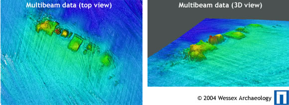
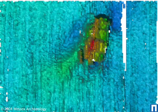
Multibeam sonar was used to gather bathymetric data from the wreck sites for the creation of 3D terrain models and georeferenced 2D images. Magnetometer surveys were conducted to establish the magnetic signature of the sites. Sub bottom profiler surveys served to provide information on the general geological stratigraphy on the sites and to indicate the presence of buried material.
Multibeam
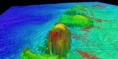
Multibeam sonar ensonifies a swath of seabed beneath and to either side of the survey vessel, deriving continuous and well- positioned spot heights for many thousands of points on the seabed as the vessel moves forward.
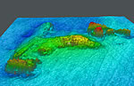
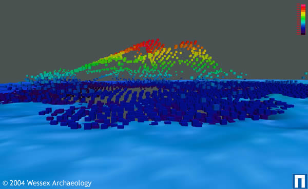
From multibeam data, 3D terrain models can readily be created. Depressions and features projecting from the seabed can be displayed and quantified in terms of their dimensions.
For the "Wrecks on the seabed" project a Reson SeaBat 8125 multibeam echosounder was used.
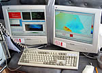
The survey data was processed by Wessex Archaeology using the IVS Fledermaus visualization system.
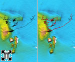
The results were 3D terrain models, 3D fly through movies and 2D georeferenced images. The 2D images were used as a base for site plans. Divers used prominent features as datum points and carried out range and bearing measurements or used offset and triangulation to map other objects, as can be seen from this plan of the Portland Stone Wreck.
Magnetometer
Marine magnetometers detect variations in the Earth's total magnetic field. These variations may be caused by the presence of ferrous material on or under the seabed, geological features or diurnal variations in the Earth's magnetic field due to solar activity. Marine magnetic surveying has become a standard technique for mapping the location of ferrous material on the seabed.
Magnetometers are usually towed behind the survey vessel at a sufficient distance to avoid any magnetic disturbance caused by the survey vessel itself.
For the 2003 fieldwork, a Geometrics G-881 caesium vapour magnetometer was deployed on each wrecksite at a linespacing in the order of 10-20m.
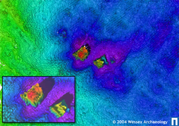
In the course of post processing the magnetometer data was imported into Fledermaus and overlayed over multibeam data to show the relationship between the anomaly and the visible wreck site.
Sub bottom profiler
Sub bottom profilers work on the same principle as simple echosounders, but use much lower frequency acoustic energy. The acoustic pulses penetrate below the seabed and into the sediment. Returning echoes from sub bottom features such as geological stratas or buried material create a trace on paper and in the digital record.
A number of different sub bottom profiling systems are available. These are categorised by the frequency content of transmitted pulses.
Low frequency systems, often called boomers achieve high ground penetration at low resolution, while higher frequency systems, called pingers, achieve high resolution but only limited ground penetration.
For the 2003 fieldwork, Wessex Archaeology employed an Applied Acoustics boomer plate. The survey sought to determine the geological setting of the wreck sites and to detect pieces of buried wreckage that were not visible in magnetometer, sidescan or multibeam results.
The data was processed using Coda software and then interpreted.
Diving methodology
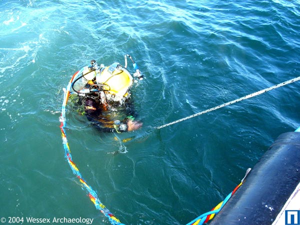
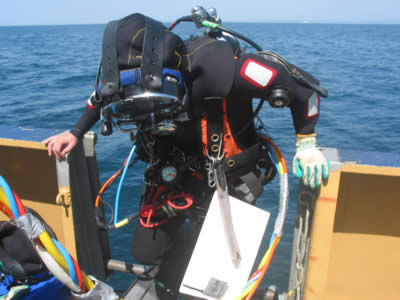
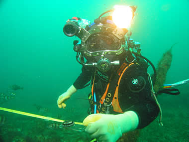
The Wessex Archaeology dive team consisted of five team members: archaeological supervisor; diving supervisor; diver; standby diver and tender. All divers held commercial diving qualifications.
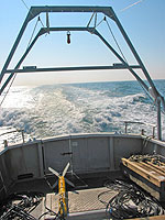
The diving support vessel EMU Surveyor was hired for all diving fieldwork in the ALSF project "Wrecks on the Seabed". Access to the water was provided by a transom gate and diving ladder at the stern.
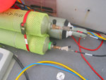
Surface Supplied Diving Equipment was used throughout the project. The air supply on board consisted of four 300bar 50l J-cylinders.
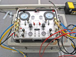
The air supply was controlled with a DIVEX two diver panel with integrated pneumofathometers. An AMRON communication box was used for diver communication.
Divers were linked to the surface by umbilicals which included air supply, pneumo tube, communication, light and camera cables. Standard KMB 28 band masks with neoprene hoods were used. Faceplate mountings held video camera and light.
Underwater recording was carried out using the hat mounted camera, handheld digital stills camera and by making measured sketches on drafting film. Watch an extract of the footage (opens your media player, MPEG1, 1.3Mb).
For each dive the wreck was marked with a buoy, before anchoring the vessel on a two point mooring for the duration of the dive. If longer fieldwork was planned, a shot was secured to a part of the wreck.
Due to strong tidal currents in the area, diving was only carried out in slack water periods.
Acoustic diver tracking
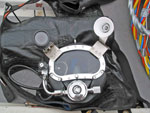
Throughout the project, diver orientation was enhanced by an acoustic USBL diver tracking system, manufactured by Sonardyne.
In this system, range and time difference measurements of sound signals emitted by a beacon attached to the diver on the seabed allow to calculate the divers position.
A transceiver assembly mounted over the side of the vessel received the sound signals. A navigation processor calculated and displayed the relative diver position. Further software packages were used to transform the relative coordinates into real world geographical coordinates and to display the diver position overlayed on a georeferenced multibeam or sidescan image of the wreck.
As the transceiver and thus the coordinate reference frame was fixed to the vessel and influenced by yaw, pitch and roll, additional equipment such as a motion reference unit and a gyrocompass had to be used to compensate for the boat’s movement and enhance tracking accuracy.
The average positioning accuracy achieved with the USBL system ranged from 2m to 6m. This made the system suitable for basic orientation on large wreck sites, but not for surveying or detailed orientation in low visibility conditions. The main factors responsible for inaccuracies were related to boat positioning and boat movement compensation rather than the acoustic tracking system itself.
Surveyed wrecks
The study area stretched from Hayling Island in Hampshire to Beachy Head in East Sussex. The environmental conditions in this area resemble the conditions that prevail in most of the aggregate dredging areas on the British south coast.
In addition to the surveys undertaken in the Year I and Year II campaigns of the project, a number of designated historic wreck sites, protected under the Protection of Wrecks Act 1973 were surveyed with multibeam sonar, magnetometer and sub bottom profiler as a project variation.
HMS A1
HMS A1 was the first submarine which was designed and built in Britain. She was commissioned in 1903, but tragically lost with all hands in a collision off the Nab light in 1904.

The submarine was raised in 1904 and then used for training and experimental purposes. HMS A1 finally disappeared during an unmanned exercise, when the tow broke. Despite of extensive searches, the Royal Navy was unable to locate the submarine. The wreck was rediscovered in 1989 and designated as a historic wreck under the Protection of Wrecks Act 1973 in 1998. Wessex Archaeology conducted a magnetometer survey, a sub bottom profiler survey and a multibeam sonar survey on the wreck site in 2003.
Hazardous
Hazardous was originally built as Le Hazardeux, a French 3rd rate, in Port Louis in 1698. She was captured by the Royal Navy in 1703 and converted to an English 4th rate of 54 guns in Portsmouth.
Hazardous was lost in November 1706, when she was run aground in Bracklesham Bay. The wreck was discovered by divers in 1977 and designated as a historic wreck under the Protection of Wrecks Act in 1986. In 2003 Wessex Archaeology carried out magnetometer, sub bottom profiler and multibeam sonar surveys on the site.
Invincible
The Invincible was a 3rd rate 74 gun ship of the line built in Rochefort in 1744. She was captured by Admiral Anson in the Battle of Finistere in 1747.
Due to her superior design she was purchased by the Royal Navy and commissioned as a 3rd rate ship of the line. In addition her lines were taken off, and two new 74 gun ships, the Valiant and the Triumph were built after her design in 1757.
In 1758 a jammed rudder caused the ship to run aground on Dean Sand. Despite several efforts the Invincible could not be made free. All guns and the crew were taken off, but the hull remained on Dean Sand.
The wreck of the Invincible was discovered in 1979 and designated in 1980.
Wessex Archaeology carried out multibeam sonar, magnetometer and sub bottom profiler surveys on the site in 2003.
Mary Rose
In 2003 Wessex Archaeology conducted a multibeam sonar, magnetometer and sub bottom profiler survey on the site of the Mary Rose.
Built in 1509, the Mary Rose was on of the bigger warships in Henry VIII fleet. She was rebuilt in 1536 and sank in 1545 during an engagement with the French fleet in the Solent.
The site was discovered by Alexander McKee in 1971, designated in 1974, and then excavated and partly raised. The main part of the hull is now being conserved in the Portsmouth Historic Dockyard, but the bow section was not raised during the main excavation and there is high potential for the survival of artefacts and features outside of the excavation area.
The Mary Rose site is currently being excavated by the Mary Rose Trust.
Site 5001
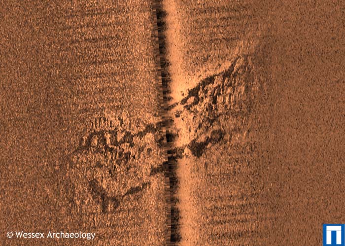
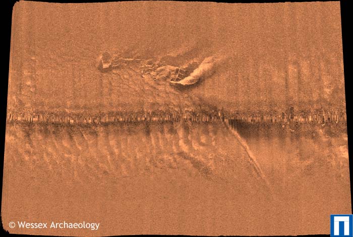
Site 5001 was surveyed with a sidescan sonar in August 2002. The wreck is said to be the remains of a World War II B-24 Liberator bomber. It is not marked on charts.
Site 5002 B17- Bomber
Summary
Wreck 5002, the remains of a Second World War Bomber, lies in 16m deep water SSW of Newhaven. The wreck was first mentioned in 1975, when a SCUBA diver failed to surface after a dive. This accident led to partial dismantling of the wreck by the Royal Navy. In 2002 and 2003 Wessex Archaeology carried out a geophysical and diving assessment of the site to confirm the aircraft type identification and to establish the extent of the site. Like all aircraft lost in military service, the site is protected under the Protection of Military Remains Act 1986.
Results
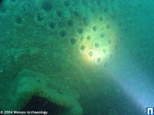
A close inspection of the aircraft engines on site confirmed the identification of site 5002 as a B-17 bomber. The B-17 was one of the most common daylight bombers during the 2nd World War. It was used by the RAF as well as by the USAF from many British airfields for bombing raids to France and Germany.
The first B-17’s (model C) were employed in the European war theatre in 1941. A series of amendments and improvements led to the construction of the B-17 G from 1943. Altogether 8680 B-17’s of this model were built. 1301 of these were either shot down, crashed or were ditched. The B-17 G had a wingspan of 31.6 m, a length of 22.8m and a height of 5.8m. It weighed 22475 kg. The maximum speed was 295 mph at a height of 7625m. The range of the bomber was 1760 km. B-17 G’s were armed with 13 .50 cal machine guns and carried 2724 kg of bombs.
Further details on the histoy of the B-17 bomber can be found at http://b17bomber.de/english/index.php.
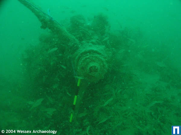
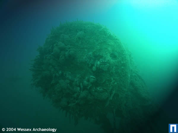
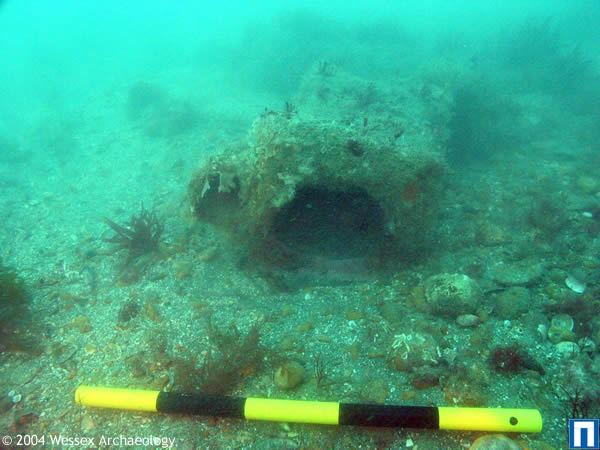
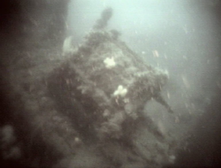
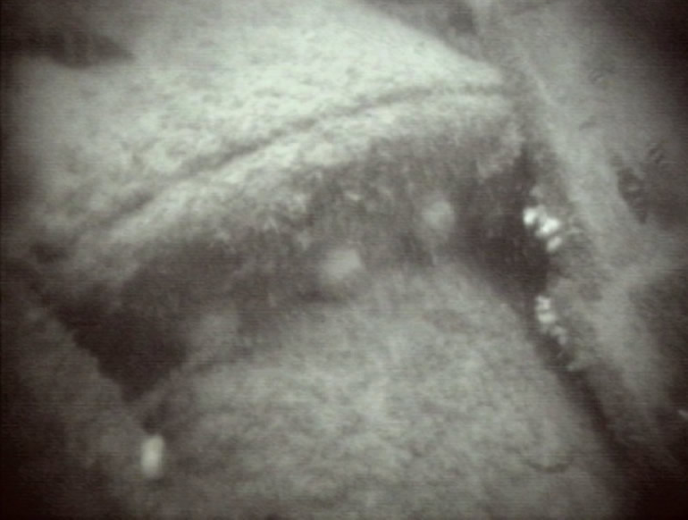
Engines
One of the three 9 cylinder radial air cooled Wright Cyclone GR 1820 engines on site. Two propeller blades are still attached and the variable propeller pitch mechanism is visible.
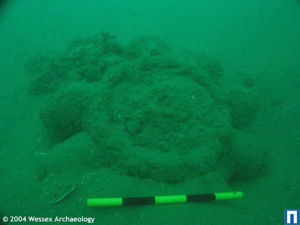
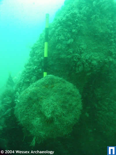
The second engine, the propeller is missing and the engine block is partly buried.
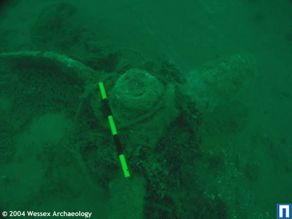
Third engine with propeller attached. The engine block is buried.
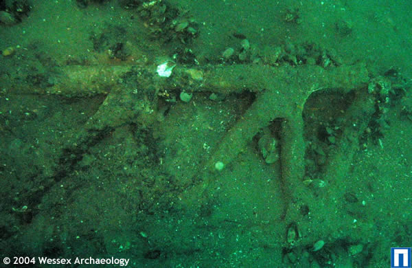
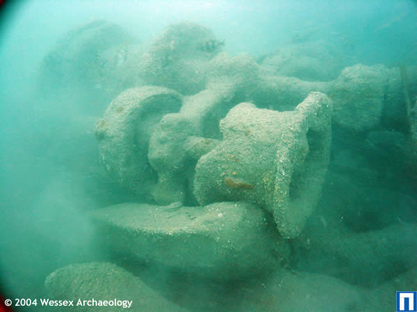
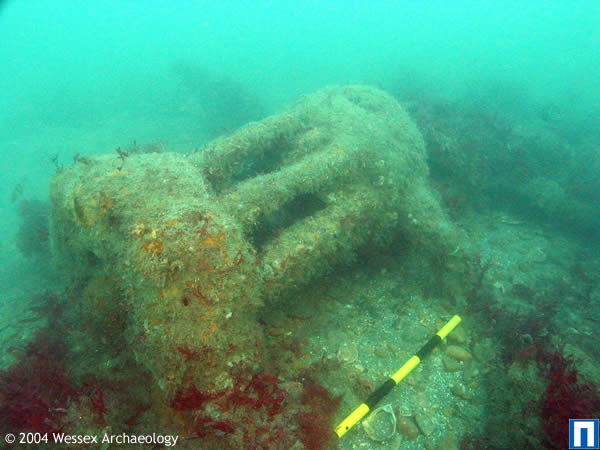
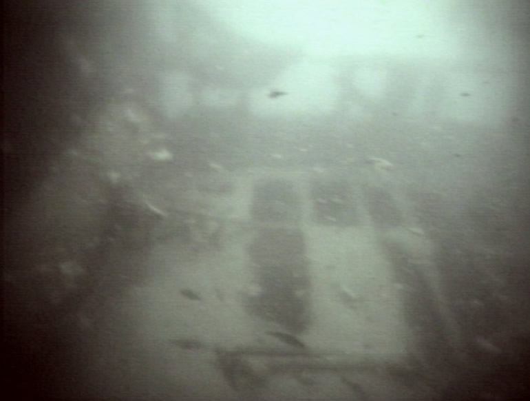
Wing structure
Tubular frame structure, probably part of the internal wing framing.
Site 5003
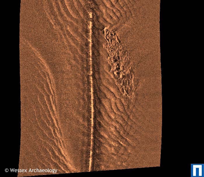
Wreck 5003 was surveyed with sidescan sonar and magnetometer in 2002. The wreck appeared to be 75m long and 15m wide, standing 4.8m proud of the seabed. A significant magnetic anomaly is associated with the wreck.
The site was not subject to an archaeological dive survey and the wreck has not been identified.
Site 5004 Concha
Summary
Wreck site 5004 is situated SSE of Littlehampton in West Sussex. The wreck lies in 10.7m (CD) of water on a sandy/ gravelly seabed. The wreck was discovered by the UKHO in 1975 at a depth of 18m. In 1984 the site was dived for the UKHO and described as a big metal wreck with iron propeller and a cargo of iron ore.
Wessex Archaeology conducted a geophysical survey on the site in 2002 and 2003 and carried out documentary research.
Results
Using documentary sources and measurements taken off the multibeam data, wreck 5004 could be identified as the Belgian steamer Concha.
The Concha was en route from Carloforte in Sardinia to Antwerp with a cargo of iron, copper and tin ore, when she collided with the steamer Saint Filians from Liverpool on the 20th August 1897. Nine sailors died in the accident. The expensive cargo of tin and copper ore was probably salvaged after the accident, while the iron ore remained in the wreck.
Site 5005
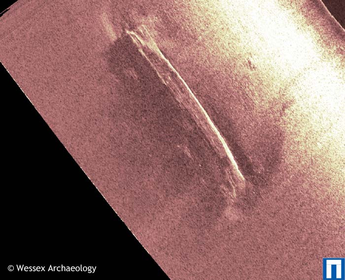
Wreck 5005 is known as the 'Gun Wreck', but may be the remains of the Umba, a Rostock built merchant vessel, which was taken as a prize by the British in World War I, and torpedoed by a German submarine in 1918.
The wreck was surveyed with sidescan and magnetometer in 2002. The sidescan data shows a large wreck (96m x 13m) which appears to be largely buried. The magnetometer data confirms that the wreck is built from steel or iron. No diving took place on the wreck site.
Site 5006 Devon Coast
Summary
The wreck of the Devon Coast lies in 16m of water (CD) south of Cuckmere Haven in East Sussex. It was found by the UKHO in 1976 and identified by means of a builders plate in 1981. In 2002 and 2003 Wessex Archaeology carried out a number of geophysical and diving surveys with the aim to test methodologies, to confirm the identification and to obtain details on the construction and appearance of the "Devon Coast".
Results
The survey confirmed the identification of the Devon Coast and produced a basic plan of the wrecksite. The Devon Coast sank in a collision with the steamer Jeanie from Liverpool on the 4th of November 1908
After the collision she was taken in tow by the Jeanie, but she sank before the protected waters of Cuckmere Haven could be reached.
Vessel specifications for the Devon Coast were obtained from Lloyds Register and the British Mercantile Navy List.
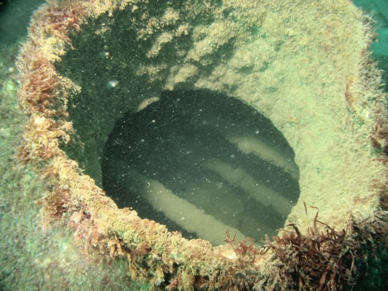
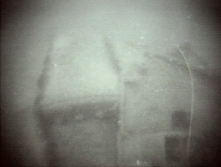
Boiler and donkey boiler
The large cylindrical main scotch boiler of the ship can still be found in its original location in the stern area. Two square furnace doors and the ends of steam tubes are visible on its northern face. The donkey boiler has collapsed and lies in front of the main boiler.
Bollard and fairlead
The collapsed bow area seems to be lying on its side. On the now vertical deck, a bollard and fairlead were observed.
Cargo winch
One of the cargo winches of the Devon Coast is still standing upright on top of the cargo of cement bags where the deck collapsed.
Engine
The remains of the triple expansion steam engine with the propeller shaft still attached can be seen aft of the boiler. The propeller is missing and has probably been salvaged.
Site 5007
Wreck 5007 is an unidentified and very broken up vessel. It was surveyed with sidescan sonar and magnetometer in 2002. The magnetometer data indicates that the wreck is made of ferrous metal.
The sidescan image shows a largely buried wreck, measuring 85m x 15m. A diver survey of the site was carried out in 2002. The diver observations confirmed that the wreck was dispersed with explosives. The hull consists of riveted steel plates. A boiler was observed in the wreck.
Site 5008
According to UKHO records, wreck 5008 represents the remains of an unknown trawler, lying on the starboard side. The wreck was surveyed and dived by Wessex Archaeology in 2002.
Wessex Archaeology divers described the wreck as the remains of a riveted hull steam trawler. Among other features, a proportion of the funnel leading into the engine room was observed.
Site 5009 Talis
Summary
Wrecksite 5009 is situated south-east of Beachy Head in East Sussex in 15.2m deep water (CD). The wreck was discovered by HMS Goldfinch in 1906, when a mast was showing above the surface. It was charted as dangerous wreck and the mast was removed in October 1906. In dive guides the wreck is usually called "1906 wreck" after its year of discovery. As adverse weather conditions on site prevented diving, Wessex Archaeology carried out sidescan and multibeam sonar surveys in 2002 and 2003.
Results
The approximate vessel dimensions were taken off the sidescan and multibeam data. With this information and the wreck position, documentary sources were consulted to identify the wreck.
In the Shipwreck Index of the British Isles (Larn 1997), the Swedish steamer Talis was listed, which sank on the 22nd July 1906 at an approximate position of 50º 42’ N and 00º 26’ E near the Royal Sovereign Lightship in a collision with the SS Roman from Liverpool.
The Talis was carrying coal from Llanelly to Gävle in Sweden. There is no mention of casualties in the incident. The location of the wreck site as well as the dimensions measured on the multibeam and sidescan data correspond with the specification of the Talis. The iron propeller, indicating single screw propulsion also supports this interpretation. The fact that the masts of the wreck were still visible in August 1906 indicates a recent sinking, not more than a few weeks before the sighting. The date of sinking of the Talis fits this hyothesis. Although very little geophysical and archaeological information exists for this wreck site, the wreck can, with a fair degree of certainty, be identified as the Swedish steamship Talis.
With the name of the ship, the Lloyds Register of British and Foreign Shipping for the year 1906 was consulted to find out more details about the Talis.
Site 5010
Summary
Wreck site 5010 was located north-east of the Nab Tower in the deep draught vessel approach to the Nab Channel. The wreck lies in 13.6m deep water (CD) on a sandy seabed.
The site was discovered by the UKHO in 1969 and charted. It was described as a broken up wooden steamship. A boiler and a four-bladed propeller were found on site. Wessex Archaeology carried out geophysical surveys in 2002 and 2003 and a brief assessment dive in 2002. No further diving evaluations were undertaken on the wrecksite.
Results
The evidence gathered from documentary sources and the Wessex Archaeology field assessment indicates that the wreck represents a steamship with single screw propulsion and scotch boiler. The ship might have been of composite build. These facts suggest a date of building after 1862, the year the scotch boiler was invented and patented.
To date no recorded losses corresponding to the archaeological evidence have been found.
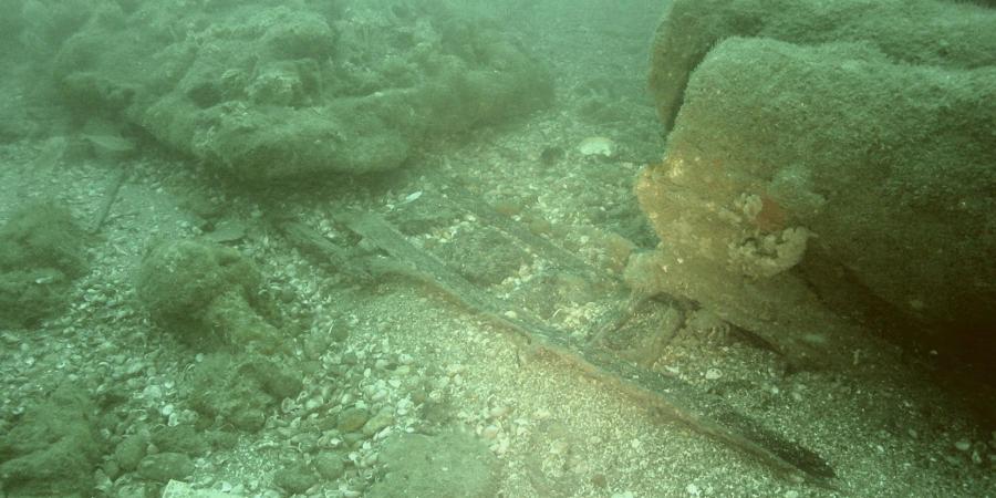
Site 5011 The Portland Stone Wreck
Summary
Site 5011 lies in 7.7m deep water (CD) east of Selsey Bill an an area called "The Park". The seabed around the site consists of gravel. The wreck was located by the UKHO in 1976 and charted as an obstruction. In 1982 divers described it as a "very old wooden vessel".
A number of geophysical surveys as well as a short diving assessment and a longer evaluation were carried out by Wessex Archaeology in 2002 and 2003. The fieldwork involved the documentation of diagnostic features on site using drawing and sketches as well as underwater photography and video.
Results
The archaeological evidence collected during the WA surveys helped to characterise and interpret the wrecksite. A final identification of the wreck could not be achieved.
The so called Portland Stone Wreck was a carvel built, single masted sailing vessel, with the mast situated well forward in the front third of the vessel. The ship was approximately 15-16m long and 5.5m wide. It was fairly flat bottomed.
It probably represents the remains of a sailing barge or barge-like vessel, which sank in the second half of the 19th century with a cargo of Portland stone.
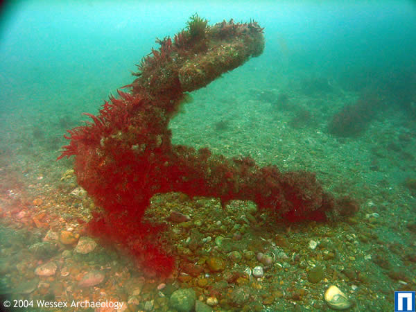
Anchor
A small iron admiralty type anchor located in the bow section. The stock is buried.
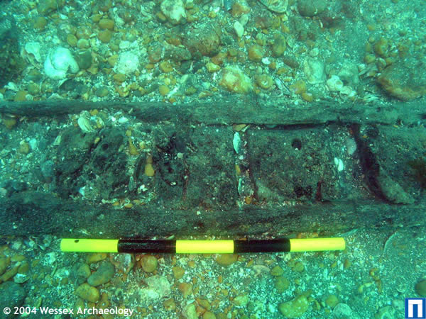
Port side
Due to the angle of the hull on the seabed, the portside is better preserved than the starboard side. Frames, outer planks and ceiling planks are visible almost from bow to stern.
Possible pump tube
A hollow iron pipe was found forward of the stove. This is probably the pump pipe of the vessels bilge pump.
Starboard bow
The starboard side is eroded to the level of the floor timbers. Outer planking and floor timbers are visible on the seabed. All outer planks were fastened with trenails.
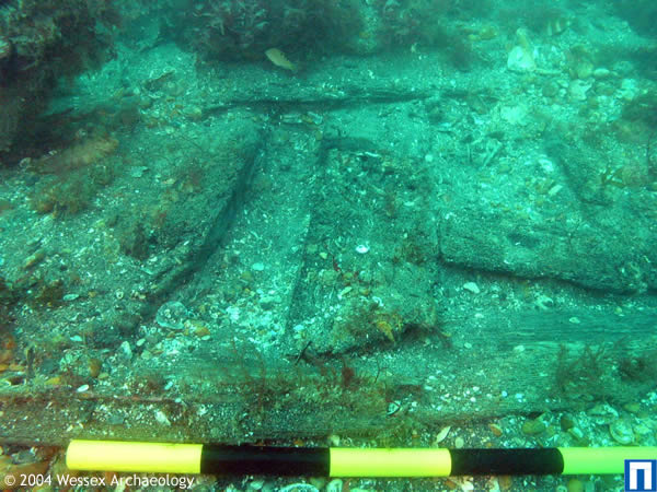
Stone Cargo
The cargo consisted of large stone slabs, presumably of Portland stone. The stones are still stacked in the position of the former hold. They are angled towards the starboard side.
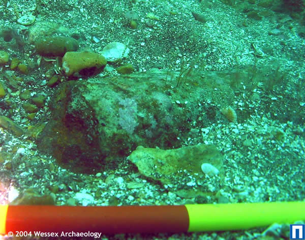
Stove
A small cast iron stove was found in the stern area of the vessel. The position of the stove within the site indicates the location of the aft cabin.
Winch
An iron winch case was observed on the portside, about 3m from the presumed bow
Site 5013 The Bottle Wreck
Summary
Wrecksite 5013 is situated south-east of Selsey Bill in the Outer Owers. The general depth on site is 19.7m (CD). The wreck was first located by the Admiralty in 1944. In 1985 UKHO divers examined the site and described it as the remains of a wooden sailing barge with a cargo of cast-iron pipes, wine and beer bottles. The wreck has been extensively dived by sports divers and a number of items have been lifted from the site. Some artefacts can be seen in Littlehampton Museum. Wessex Archaeology carried out a geophysical survey of the wreck, but the site could only be dived once due to adverse weather conditions.
Results
The multibeam data shows a 14m long and ca. 6m wide stepped anomaly with a maximum height of 2m on the seabed. According to Wessex Archaeology diver observations this is probably the main cargo of stacked cast iron pipes, possibly gas pipes. No ship structure was observed during the assessment dive.
A consultation of various documentary sources did not produce any results. It is only through secondary sources that the wreck can be characterised as a small sailing coaster or barge that sank in the beginning of the 19th century. A length over 14m and a breadth over 6m has to be assumed for the vessel.
Site 5031
Wreck 5031 was surveyed with sidescan sonar and magnetometer in 2002. On the sidescan data the wreck seemed to be broken in two parts. It is lying on the port side. A debris scatter is visible around the site. Wreck and associated debris scatter measure 76m x 16m. The site was not dived in 2002.
Site 5043
A sidescan anomaly picked up during the 2002 wreck survey is the wreck of HMS Impregnable, a 98 gun ship built in Deptford in 1786. The sidescan data shows a number of rectangular features on the seabed. The magnetometer data indicates that these features are of ferrous metal.
The site was not dived in 2002, but it was investigated by the Hampshire and Wight Trust for Maritime Archaeology.
Round two
Year one dive and geophysics
Project background
The aim of Round 2 of Wrecks on the Seabed is to provide industry, regulators and contractors with a framework for a staged approach to the investigation of wreck sites. Such a framework is important when considering the time and cost of marine investigations. It is also helps effective communication between industry, regulators and contractors. The project design for Round 2 of Wrecks on the Seabed builds on the experience of Round 1 of the project.
The project addresses the following aspects of wreck site investigation:
-
A geophysical survey of a 2x2km area of seabed presents an opportunity to develop methodologies for the survey of ephemeral wreck sites.
-
With the dredging industry moving into deeper water, one of the key points emerging from industry is the applicability of wreck investigation methods to greater water depths. The geophysical and Remotely Operated Vehicle survey of three unknown wreck sites in water depths between 46 and 60m will serve as a basis for the development of effective methods for assessing, evaluating and recording wreck sites in deeper water.
-
As most of the problems encountered during the diving fieldwork of Round 1 were related to the size of the diving vessel, a larger Remotely Operated Vehicle / diving support vessel will be deployed in Round 2 of the project. An analysis of the costs and benefits using larger vessels will be carried out.
-
Four of the wreck sites investigated by divers in Round 1 of the project will be revisited with an Remotely Operted Vehicle in Round 2. This will allow a direct comparison of Remotely Operated Vehicle and diver based results.
-
The project results will be made available to the public through web pages, brochures, lectures, conferences and diver information packs for recreational divers.
As the project is specifically tailored to the requirements of marine aggregate dredging, the study areas and sites chosen are all situated close to existing or intended marine aggregate extraction areas.
Round two methodology
The MV Flatholm from Coastline Surveys Limited was used as the work support vessel throughout the 2005 field sessions. The Flatholm is a converted harbour tug, built in Japan in 1976. The vessel has a length over all of 23.3m, a breadth over all of 8.0m and a 2.6m draft.
The Wessex Archaeology Remotely Operated Vehicle and diving operations were directed from a control room, permanently installed on deck aft of the superstructure.
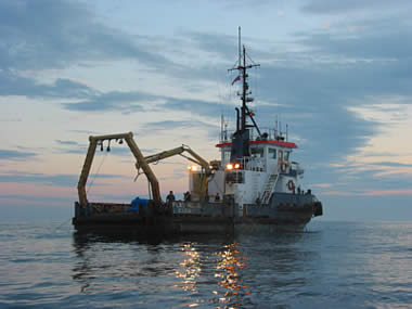
Throughout the Remotely Operated Vehicle session Flatholm was moored on a four point mooring above the wrecks to be surveyed.
The vessel's two bow anchors were used at the front and two 200kg high power holding anchors with short lengths of chain were deployed at the stern. Two hydraulic winches were used to handle the stern mooring.
For the mooring procedure a computer file (.dxf) showing the wreck outline visible in the geophysical survey was displayed in the vessel navigation software package on the bridge. Points were taken where anchors were to be dropped, so as to avoid damage to the wreck. However it was not always possible to avoid mooring wires crossing the wreck site.
As the two 200kg anchors used as stern mooring during the Remotely Operated Vehicle session proved insufficient to hold MV Flatholm on station in strong tides and less favourable weather conditions, two sinkers of 2t and 3t respectively were bought for the diving session.
A 40m length of chain with a buoy and a shackle at the end was attached to each sinker. The use of sinkers required a lengthy mooring procedure to avoid dragging long wires through the water and damaging wreck sites.
On arrival on site, the two buoyed sinkers were dropped on one side of the wreck and their positions marked. The vessel than deployed the bow anchors on the other side of the wreck site and then dropped back. Then the stern winch wires were connected to the sinkers using a small rigid inflatable boat.
Acoustic tracking system
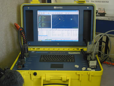
An Ultra Short Baseline (USBL) SCOUT acoustic tracking system from Sonardyne was used during all fieldwork sessions to track the Remotely Operated Vehicle and divers.
The SCOUT system consists of three main components: the vessel mounted acoustic transceiver, one or more Remotely Operated Vehicle or diver mounted transponders and the surface command module running the control software.
In a USBL system, the position of subsea targets is calculated by measuring range and bearing from the vessel mounted transceiver to the submerged transponder, which emits acoustic signals.
In a short baseline system, only one transducer (transponder on the seabed) transmits sound, but many transducers on the surface receive signals. In a USBL system such as SCOUT this array of transducers is built into a single transceiver assembly. The baselines between the individual transducers are very (ultra) short, usually in the range of centimetres.
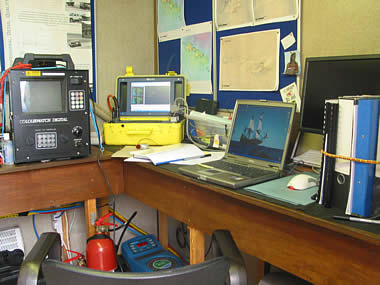
The waterproof and portable surface command module running the SCOUT USBL software was installed in the control room.
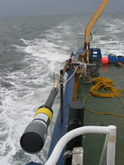
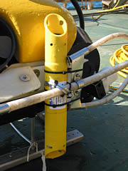
The SCOUT USBL Transceiver was mounted on a pole over the side of Flatholm. In order to provide maximum stability for the transceiver the pole had a diameter of 10cm and was attached to a bracket welded onto the rail and supported by another bracket further down the ship’s side. The pole could be swivelled up when Flatholm was in passage.
SCOUT’s very light and rugged Type 7815 HF transponders could easily be attached to either the Remotely Operated Vehicle or diver umbilicals.
The transponder worked on frequencies between 35 and 55kHz. The stated operating range for the system was 500m and the acoustic coverage was +/- 90 degrees below the transceiver.
Recording system
Even when moored, a vessel yaws, pitches and rolls. As the calculated diver/Remotely Operated Vehicle position is based on the transceiver position, this movement introduces inaccuracies into the positioning and has to be compensated. The SCOUT system allows tracking in two modes: The transceiver includes an internal heading and attitude sensor, which can be used for compensation. Alternatively an external motion reference unit (MRU) and a gyrocompass can be used to compensate for vessel movements.
Using the system on internal sensors is easier, as no external instruments have to be configured, but this decreases the stated accuracy of the system from ± 0.5% of the slant range to ± 2.75% of the slant range.
For both the Remotely Operated Vehicle and diver fieldwork sessions, an external MRU and gyrocompass were installed on the Flatholm.
A TSS HRP-10 MRU was fitted in the survey container. X, Y and Z offset values to the transceiver were entered in the SCOUT software.
An ASG Brown Meridian Surveyor gyrocompass was also installed in the survey container and positioned exactly parallel to the vessel's lubber line.
An onboard GPS provided positioning information. The GPS was a CSI Vector Sensor Differential GPS capable of sub-metre accuracy.
Prior to the fieldwork, all instruments were surveyed on the vessel with the help of a total station by a Wessex Archaeology surveyor to achieve the highest possible positioning accuracy. The offset values to the USBL transceiver were entered into the SCOUT software. All external instruments were connected to the SCOUT surface command module.
Both external and internal sensors had to be calibrated before use. This required the Flatholm to sail predefined patterns around a transponder on the seabed and to steam a full 360 degree circle. A calibration wizard in the SCOUT software automatically applied the necessary corrections to the USBL settings.
Since 2002, Wessex Archaeology has developed a Microsoft Access based diver recording system known as ‘DIVA’ which can be used for real time recording of three-dimensional positions and information in conjunction with the mapping programme ESRI ArcGIS 9.0.
DIVA consists of a Microsoft Access database which stores the information, and a GIS interface for graphic display. This system was used in Round 1 of the project and has since been further improved.
The position of the tracked vehicle or diver is output from the Sonardyne SCOUT surface command module in real world co-ordinates and can consequently be displayed in real time on top of geophysical survey data in ArcGIS 9. The vehicle or diver track can also be displayed and saved separately.
To allow integration with the previously acquired geophysical survey data, Universal Transverse Mercator (UTM) coordinates, based on the WGS84 datum and the WGS84 ellipsoid were used for display and recording. The targeted wrecks were spread over UTM zones 30N and 31N.
A laptop running DIVA and ArcGIS was set up in the survey container, so that the recorder could see the screens showing the underwater footage being collected by the ROV and divers.
Observations made by divers or recorded from the Remotely Operated Vehicle video feed can be entered into the database by the recorder. These observations, stored in the DIVA database, include the three-dimensional position, comments typed in by the recorder and mapping labels for the display in the GIS system.
Observations can be taken as quick, but less accurate, spot fixes, or as average fixes. Average fixes obtain a number of positions over a short period of time and calculate an average position for the diver or tracked vehicle using a software application developed by Wessex Archaeology and known as Accu-fix. The more accurate average fixes were generally used for recording datum points and important features on the wrecks.
Diver observations can be displayed as different layers in ArcGIS, grouped for example by mapping labels, observation type, etc.
A summary form allows the archaeological supervisor to summarise individual dives, whole events and monuments. The diver can also enter archaeological, environmental and operational summaries. Paper records such as drawings can be referenced to individual diver observations.
A general log allows the archaeological supervisor to keep track of daily events, working hours, weather forecast and tidal predictions.
Records of earlier events, such as the Round 1 diving or the collection of geophysical data were readily available in the DIVA database. This was a useful source of reference and comparison, especially where earlier diver observations were concerned.
ROV operations
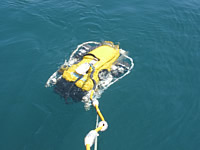
The Remotely Operated Vehicle (ROV) survey of shallow wreck sites took place between the 11 and 26 June 2005. The survey was carried out from the MV Flatholm, Coastline Survey with two Wessex Archaeology staff acting as archaeological supervisor / tender and recording system operator to carry out the recording, and an external ROV operator.
The ROV and pilot were supplied by SUBCO Underwater Equipment. A Seaeye 600 high power inspection and observation ROV was used throughout the project.
The 1m long and 76cm wide ROV weighed 75kg. It was powered by 4 thrusters which provided a maximum forward speed of 2.5 knots. The ROV was supplied with 150m of umbilical. The maximum payload was 10kg.
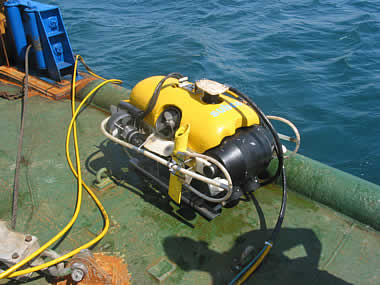
The ROV had two integrated cameras: a PAL colour camera; and a low light black and white (B/W) camera. Two 150 watt lights were dimmable and could be tilted together with the cameras to ± 80 degrees.
The ROV was equipped with forward scanning sonar for navigation, a built in fluxgate compass and a digital depth gauge. Information from these instruments could be displayed over the video output.
The surface controls consisted of an isolation transformer, the main ROV surface unit for power distribution, a hand controller with joystick, two screens and a Panasonic digital video capture unit. Video was recorded on miniDV tapes.
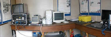
The ROV surface unit was installed in the survey container on deck. The umbilical was stowed on deck. Even though the ROV could be safely handled manually it was usually launched and recovered with the crane on deck.
Diving operations
The diving survey was split in two units of 15 days with a six day break in between and took place between 4 July and 8 August 2005. Again MV Flatholm of Coastline Surveys was used as support vessel. The project staff consisted of five archaeologists and three crew aboard MV Flatholm. The archaeological team consisted of four divers and an archaeological recorder. Diving roles were rotated within the team. Two divers were appointed as diving supervisors.
All dives were conducted using surface supplied diving equipment with Kirby Morgan 28 band masks.
The diving panel, communication box and video recording equipment were set up in the survey container next to the recording computers and the SCOUT system. The air supply consisted of five 300bar J-bottles secured to the outside of the survey container. After each dive the cylinders were recharged using an onboard diesel HP compressor.
On the starboard side of the vessel a gate was cut into the rail to provide safe access to the water via a diving ladder. The umbilicals were stowed on the open working deck.
The dive team generally consisted of diving supervisor and recording system operator in the survey container, standby diver and tender on deck and one diver in the water. On some of the shallower sites the standby diver was used in-water alongside the main diver to aid with recording or to obtain digital video and stills footage of the main diver.
Every dive was recorded on miniDV tape using a colourwatch digital video system with hat mounted camera. A Canon Powershot G2 in Ikelite housing with Ikelite DS 125 substrobe was used to take digital still photographs. A .56 Sea and Sea wide-angle lens allowed the photography of larger objects from close distances.
On night dives and deeper sites with low visibility a 100 Watt Lumb Bros FIII underwater torch was employed.
In addition to the diver recording system based on acoustic tracking, conventional recording methods, such as offset drawing, were used on the dived wreck sites.
Depending on the desired level of recording, underwater photography, videography, sketches and drawings were used. Trilateration and offset measurements were acquired with folding rules or tape measures.
You can see how the methods worked by looking at the Bottle Wreck. This wreck was recorded using traditional marine archaeologcial methods. A 32m by 10m grid was established around the visible remains of shipwreck and cargo. The pipe cargo mound and individual artefacts were then drawn in relation to the grid using offset and trilateration methods. To link the site grid to real world co-ordinates accurate fix points were taken for each of the grid corner points with the USBL system. To speed up the drawing and recording process, measurements were obtained by the diver, but the drawing was carried out by the supervisor on the surface. This was done using the live video link provided by the colourwatch system.
Remotely Operated Vehicle Fieldwork Summary
The work support vessel MV Flatholm was mobilised on 11 June 2005 at Lowestoft. The acoustic tracking system was installed and secondary instruments such as GPS and gyrocompass measured in. After loading and setting up the Remotely Operated Vehicle equipment, a test dive was conducted in Lowestoft harbour.
The transit to site took place on the 12th June 2005, and the first wreck was surveyed on the 13th June.
Altogether 20 Remotely Operated Vehicle dives were conducted on seven different sites in 10 days. Two days were down days due to strong winds (above force 6). The total bottom time for the 20 conducted dives is 1431 minutes, or 23.85 hours. The table below provides further details of the sites dived by Remotely Operated Vehicle:
|
WA ID |
Wreck Name |
Dive Days |
Down Days |
No of Dives |
Bottom Time/min |
|
5004 |
SS Concha |
2 |
- |
3 |
340 |
|
5005 |
SS Umba |
2 |
- |
3 |
241 |
|
5006 |
SS Devon Coast |
2 |
- |
3 |
54 |
|
5009 |
Unknown |
1 |
- |
3 |
280 |
|
5011 |
Unknown |
2 |
1 |
4 |
182 |
|
5013 |
Unknown |
1 |
1 |
2 |
200 |
|
5014 |
SV Thomas Lawrence |
1 |
- |
1 |
94 |
Diving Fieldwork Summary
At the start of the first diving session, unfavourable weather conditions forced MV Flatholm to stay in Lowestoft, so that the diving equipment had to be mobilised in Lowestoft instead of Shoreham as planned. Five days fieldwork time were lost due to weather at the start of the session.
The remaining session was spent on site 5013, the so called ‘Bottle Wreck’. On the second session, the equipment was mobilised and demobilised in Shoreham. Two wrecks, site 5009, the ‘1906 Wreck’ and site 5004, the ‘Concha’ were surveyed.
Altogether 55 dives were conducted on three different sites in 19 days. Nine days were down days due to bad weather or technical defects. The total bottom time for the 55 dives is 2295 minutes or 38.25 hours. The table below provides further details on the sites that were dived:
|
WA ID |
Wreck Name |
Dive Days |
Down Days |
No of Dives |
Bottom Time/min |
|
5004 |
SS Concha |
5 |
2 |
13 |
675 |
|
5009 |
Unknown |
6 |
2 |
13 |
455 |
|
5013 |
Unknown |
8 |
5 |
29 |
1165 |
Surveyed wrecks
Site 5004 The Ore Wreck
Location
The Ore Wreck is located 7.5nm SSE of Littlehampton in West Sussex, between the Outer Owers and Kingmere Rocks. The wreck position is 50 40.750N, 00 28.783W (Geodetic co-ordinates, WGS 84) or E 677954.12, N 5617253.31 (UTM Zone 30N, WGS 84). The wreck lies at a general depth of 10.7m (CD). Depths experienced on site ranged from 16m to 20m.
The seabed on the site consists of sand and sandy gravel, with a covering layer of dead shells.
What is left on the seabed?
The wreck is lying on even keel with a slight list to port on a fairly flat seabed. It is orientated northwest - southeast with the bow in the southeast. As the layout of the wreck is clear, the descriptions refer to port, starboard, bow and stern.
The site, including the debris field, measures 74m x 20m. The wreck itself measures 67m x 8m. From the propeller at the stern to the first cargo hold, the wreck forms a line on the seabed, but the bow section is broken off and lying at an angle to the starboard side.
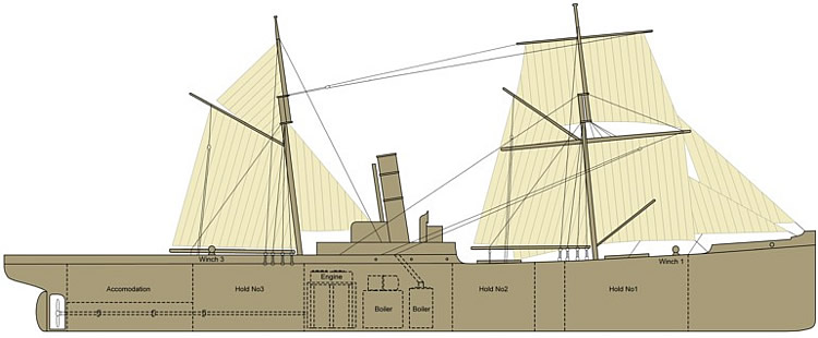
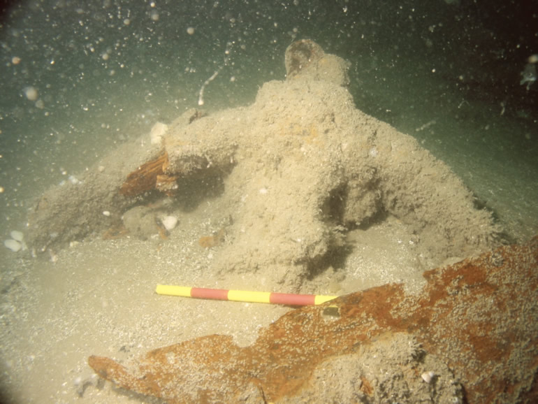
In general the hull structure is heavily eroded and where present only survives to a level of one metre proud of the seabed. The most prominent feature on the site is the engine room 20m forward of the stern. Here, the two cylinder compound steam engine and the main scotch boiler are fully intact and stand 3.36 and 3m proud of the seabed respectively.
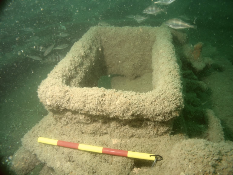
At least three cargo holds, two forward of the engine room and one aft are represented by square concreted mounds of iron ore. The aft hold or holds measure 10m by 8m and stand 2.5m proud of the seabed. No.2 hold forward of the engine room measures 6m by 9m. No.1 hold measures 8m by 8m, as does an area of debris forward of No.1 hold. The preserved part of the bow section measures 1.58m by 1.56m and stands 1.16m proud of the seabed.
Fittings and machinery originally located on the deck of the vessel, such as cargo winches and a spare propeller have collapsed and are now sitting upright on the seabed or onthe concreted cargo mounds.
While the seabed south of the wreck is fairly sterile, there is a scatter of debris along the port side of the wreck in the North.
Fittings and Machinery
Most of the ship's fittings and the machinery lie intact on the seabed. Two anchors, probably both spares, were found on site: Anchor 1 was found leaning against a debris mound forward of No.1 hold. The anchor is missing its stock. A square metal plate is bolted to one of the flukes; it is probably remains of a fastening which secured the spare anchor on deck.

The second anchor on site was found half buried beneath a steam winch (winch 1) forward of No.1 hold. The folding stock is still attached and folded in. Shank and stock length could not be determined.
Smaller in size than anchor 1, this would have been another spare anchor stowed on deck.
The anchor windlass was found upright on the seabed 6m forward of No.1 hold. It is 2.95m long and has two warping ends, each 30cm in diameter and 30cm long. Accurate measurements of the windlass were difficult to obtain due to the amount of concretion. Two heavily concreted anchor chains are still attached to the windlass.
Further aft on the wreck, three steam cargo winches were observed. The first winch (1) is situated forward of No.1 hold (view image). The second winch (2) is buried underneath iron ore cargo just to starboard of the first winch. Very little of it is exposed and it could not be recorded in detail. The third winch (3) is lying on top of a concreted cargo mound in the stern of the vessel.
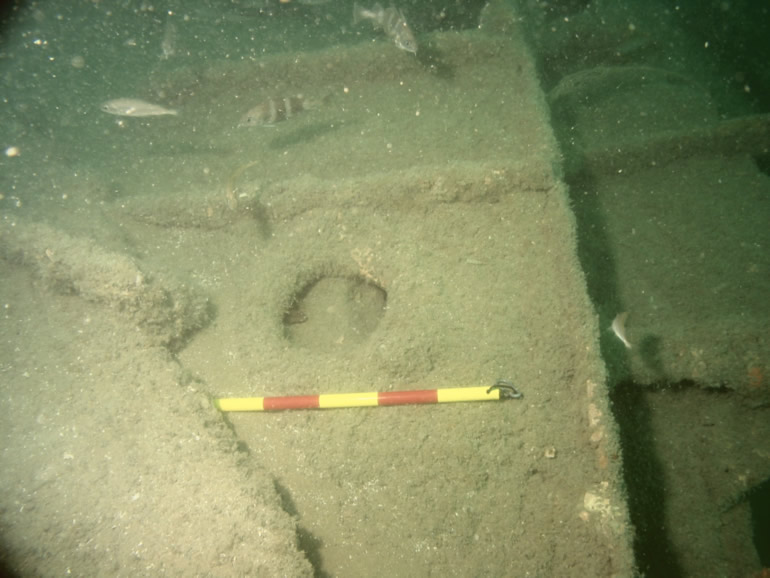
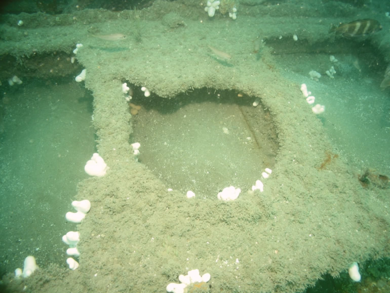
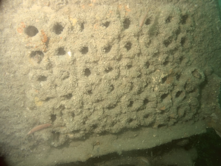
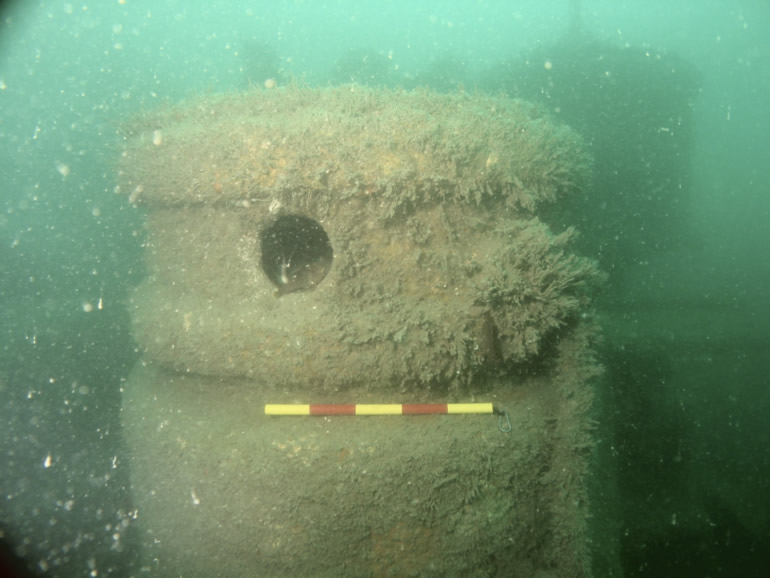
The remains of the engine room form the most well preserved part of the vessel. The main single ended scotch boiler stands upright on the seabed with a slight list to port. It is 3m in diameter and 3.18m long (view image). The boiler shell is made from riveted steel or iron plates. Stay nuts and firetubes are clearly visible. A 44cm wide opening on top of the boiler marks the original position of the steam drum. A triangular arrangement of three furnace fronts was recorded on the forward face of the boiler.
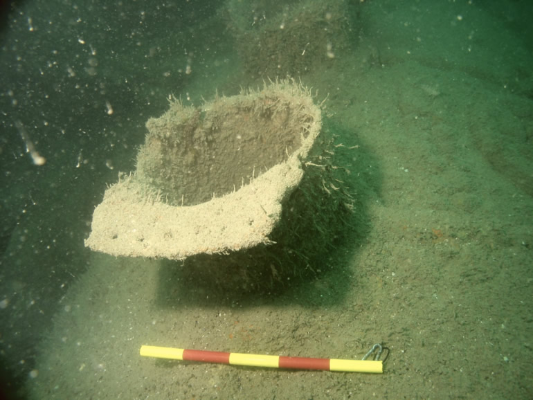
The steam drum has fallen off the top of the boiler and is now leaning against the port side. It is 2.45m long and 1.15m in diameter. The inside of the drum is visible through a large hole. The original attachment opening measures 44cm in diameter and matches the opening on top of the scotch boiler.
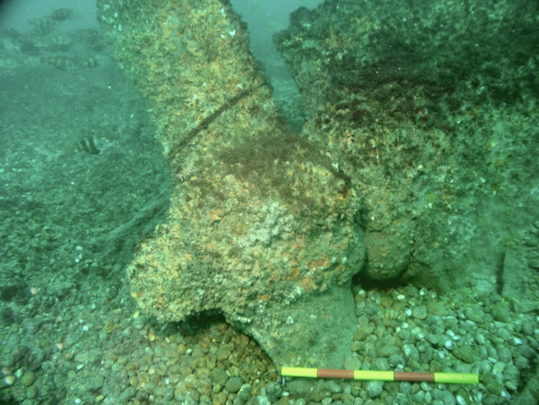
 Forward of the scotch boiler a donkey boiler has collapsed onto its side. It is 3.53m long and 1.85m in diameter. The bottom end of the boiler is still attached to a heavily eroded square base plate. On the top end the 40cm long funnel attachment is visible. The funnel was 40cm in diameter. A large hole in the side of the boiler allows the fire tubes to be seen.
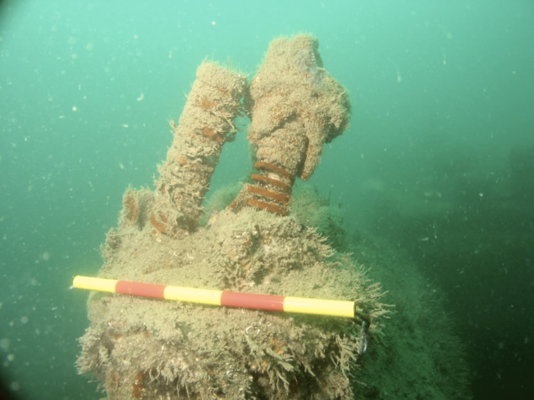
The two cylinder compound steam engine is situated just aft of the main scotch boiler (image 1, image 2). The engine is very well preserved with little marine growth. It stands 3.36m proud of the seabed. The engine casing is 2.6m long and 1.27m wide. Two cylinders are visible on top of the engine. The low pressure cylinder is 1.17m in diameter. It has an 18cm wide escape valve arrangement in the centre. The high pressure cylinder measures 91cm in diameter. The escape valve arrangement is 24cm wide. A two door condenser was seen on the aft end of the engine. All engine internals such as connecting rods and crankshaft are well preserved.
Around the engine a number of features on the seabed probably relate to the engine room, but could not be identified. A possible pump was observed to starboard of the engine casing. On the port side a spindle wheel is attached to a mount.
A spare propeller and crankshaft are lying on the cargo mound aft of the engine room. The crankshaft is 3.65m long. At one end it has a flange of 55cm diameter. The diameter of the shaft is 22cm. The cast iron four bladed spare propeller is lying at an angle on the starboard side of the cargo mound.
 At the stern of the vessel, the main cast iron propeller is still attached to the propeller shaft. It has the same dimensions as the spare propeller. The propeller shaft is exposed for ca. 8m before it disappears into the 1.1m wide tunnel. The shaft is 24cm in diameter. The stuffing box, intermediate shaft and two couplings are visible (view image).
The cargo
The vessel sank with a cargo of copper, tin and iron ore. On the seabed, the position of individual cargo holds is marked by concreted mounds of iron ore. No copper or tin were observed during the diver and Remotely Operated Vehicle surveys.
The United Kingdom Hydrographic Office wreck index mentions evidence of earlier diver salvage . It seems likely that the valuable copper and tin ore was lifted at some point after the sinking. The less valuable iron ore seems to have been left on the seabed.
Artefacts
 Very few small objects or artefacts were noted on the wreck site. Forward of No.3 hold on the starboard side of the vessel a metal wheel with straight spokes was found. This could have been part of cargo handling machinery or a fly wheel for a pump. A possible large block was observed on the starboard side forward of the main boiler. A smaller fly wheel with curved spokes is located between anchor windlass and No.1 hold.
What is the Ore wreck?
In 2003 the ore wreck was identified as the Belgian steamer Concha by Wessex Archaeology on the basis of geophysical data and documentary research. Basic information on vessel dimension and equipment were obtained from Lloyds Register. No further published information on the Concha was found to be available.
The Concha was a well decked steamer of 883 tons, built in 1877 by the Société Anonyme des Etablissements John Cockerill in Hoboken. She measured 64.98m x 8.32m x 5.09m and was equipped with a two cylinder compound steam engine. The Société Anonyme des Etablissements John Cockerill was the most influential Belgian industrial corporation of the time. It owned coal and iron mines, steelworks and a shipyard in Belgium, Luxemburg, Alsace-Lorraine and Spain. The Concha was built on the corporation yard in Hoboken and operated by the Cockerill Shipping line to transport ore. The Cockerill corporation was founded in 1817. The corporate shipyard started operations in 1824 in Antwerp. It was later moved to Hoboken, where it existed until 1982.
The Concha sank on 20th August 1897 after a collision with the Liverpool registered steam ship Saint Filians.
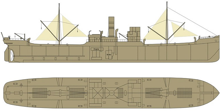
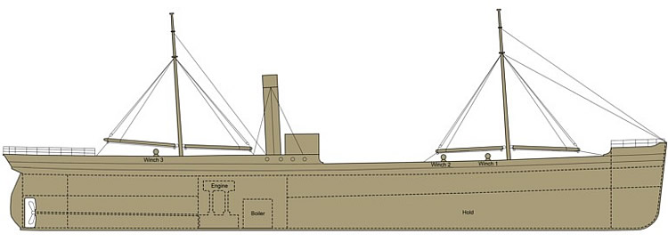
The general vessel layout of the Concha can be reconstructed from the dimensions listed in Lloyds Register. However, the information gathered during the 2005 fieldwork session allows a more accurate reconstruction of the vessel layout. The vessel outline and superstructure are based on typical designs for the period. The internal layout and the position of deck machinery are based on measurements from the geophysical data and diver observations.
Site 5005 The Gun Wreck

Location
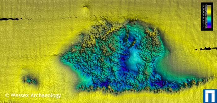
Site 5005 is located 5.5nm south of Hastings, just to the east of Hastings Shingle Bank. The wreck position is 50.77060N, 00.64781E (Geodetic co-ordinates, WGS 84) or E 334106.41, N 5626992.71 (UTM Zone 31N, WGS 84). The wreck lies at a general depth of 22m (CD). Depths experienced on site ranged from 29m to 30m. What is left on the seabed?
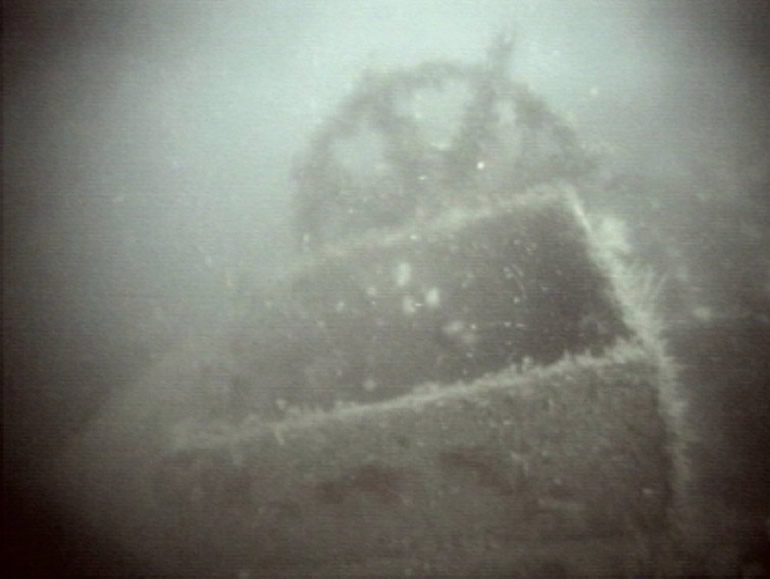
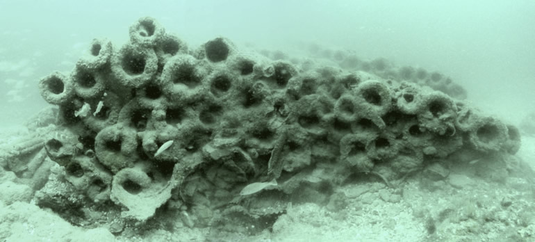
The wreck is lying on even keel with a list to starboard and is orientated WNW-ESE. The bow is in the West. The wreck site including debris is 100m long and 18m wide. The vessel stern is intact with a fully preserved poop which stands 9m proud of the seabed. There is a gun on the poop which gave the vessel its name. The aft part of the main deck is also preserved and exposed. The midship area and bow of the wreck are partially or completely buried by sand. Very few structural remains seem to be preserved in the bow area, but a very broken up anchor windlass was observed.
Portions of the deck and the top of two boilers were visible amidships. This indicates that the engine room area is completely buried.
Fittings and Machinery
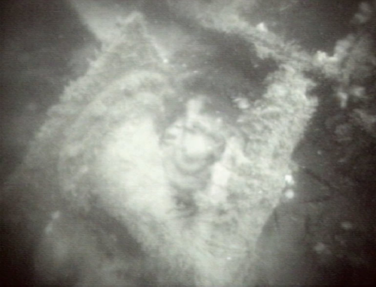
As the wreck was only surveyed by Remotely Operated Vehicle, none of the features recorded on the seabed could be measured. The stern is best preserved. The main propeller is still attached, but two of the four original blades have broken off. The rudder is missing, but parts of the tiller mechanism are still in place.
On the poop most of the original wooden deck planking is still in place. Four sets of bitts are situated around the intact emergency steering wheel (image 1, 2, 3). Forward of the wheel a cabin skylight and a mount for a small gun were seen. The gun has fallen off its mound and is lying on the starboard side of the deck (image 1, 2).
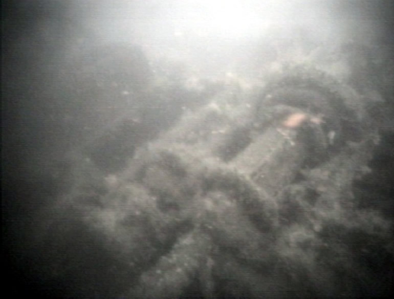
Forward of the gun mount, a steam driven winch is situated in the centre of the quarterdeck (view image). Two wire reels were seen either side of the winch (view image).
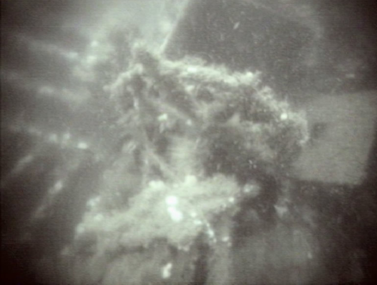
Parts of a mast or derrick have collapsed onto the main deck just below the poop (view image). In this area, the main deck is intact bar the deck planking which was probably wooden. A large four bladed spare propeller is secured to the upper deck forward of the collapsed mast.
Forward of the propeller the hatch for the aftmost cargo hold is visible. The aft hold is separated from the midship area by a bulkhead. A steam winch lies collapsed just forward of the bulkhead (view image).
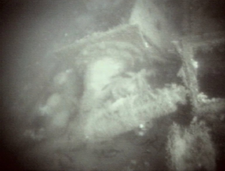
The whole midship area of the vessel is buried, but a large amount of unrecognisable debris was observed on the surrounding seabed, possibly a consequence of the torpedo explosion that led to the sinking of the vessel. The top edges of two scotch boilers, covered by bent and collapsed upper deck structure, were observed amidships (image 1, 2).
Debris and the barely visible line of starboard side frames leads towards the bow of the vessel. The bow itself is heavily damaged. The only recognisable features among the debris in this area were a broken up anchor windlass and bitts.
What is the Gun wreck?
Site 5005 is listed in the United Kingdom Hydrographic Office wreck index as steamer Umba (No. 20549). This identification is supported by The Shipwreck Index of the British Isles and the book World War One Channel Wrecks. Details on vessel specifications and history were obtained from Lloyds Register and the Schiffsregister der Neptunwerft . A plan of the vessel was published in the maritime journal Strandgut.
The Umba was built as Adelheid Menzell (Construction No. 287) in 1903 at the Neptun shipyard in Rostock, Germany. She was a schooner rigged screw steamer with a gross tonnage of 1501t, and measured 88.39m x 12.5m x 5.8m. She was equipped with a triple expansion steam engine delivering 180HP and two boilers. She had a crew of 25 and was capable of a maximum speed of 9kn.
According to Lloyds Register in 1917, the vessel had a single deck, deep framing and was equipped with electric light and wireless. The Register also gives the lengths for poop (8.53m), bridge deck (38.1m) and forecastle (10.36m).
From 1903 to 1906 Adelheid Menzell was employed on the Hamburg- China route. In 1906 the vessel was bought by the Hamburg Bremer Afrika Linie AG, and was used in the Africa trade. In 1907 she was renamed to Irmgard, renamed again to Utgard and purchased by the Deutsche Seeverkehrs A.G. in Nordenham in 1912. A plan published in Strandgut 17 shows the general layout of the Utgard and her sister ships. A photograph shows one of the sister ships, the Asgard, also built by the Neptun shipyard in 1903 moored in Wilhelmshaven in 1919.
In 1914 F.W. Fischer from Rostock bought the Utgard, but shortly thereafter she was commandeered by the Russian forces in Kovda in 1914, renamed to Umba and used by the Archangelsk Murmansk S.N. Co. Archangelsk. The vessel was armed with a single Russian 6pdr gun mounted at the stern. In 1917 the Umba was in turn confiscated by the Shipping Controller in England. In 1918 she was bought by the Ellerman's Wilson Line. She was torpedoed on 30 April 1918 while in ballast en route from Dunkirk in France to Barry Roads in south Wales. The torpedo, fired by SM UB-57, hit the Umba amidships and tore a massive hole into her side. She sank almost immediately with the loss of 20 of her crew of 25.
Site 5009 The 1906 Wreck
Click the red labels on the image below to see underwater photographs. Scroll down to read about the wreck and to the bottom of the page to see videos from the wreck.
Location
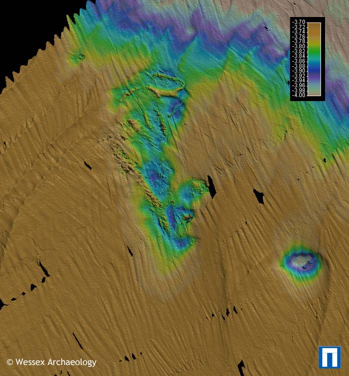
Wreck site 5009 is situated 5.56 nautical miles off Beachy Head in East Sussex, just south of the Royal Sovereign Shoals. The wreck position is 50.41.033 N, 00.22.967E (Geodetic co-ordinates, WGS 84) or E 315009.34, N 5618060.89 (UTM Zone 31N, WGS 84). The wreck lies at a general depth of 15.2m (CD). Depths experienced on site ranged from 23m to 30m.
What is left on the seabed?
The wreck is lying on even keel in southwest - northeast orientation. The stern in the southwest stands 4.5m proud of the seabed and forms the highest part of the wreck. The site measures 75m x 30m including the debris field. The wreck itself measures 66m x 8m.
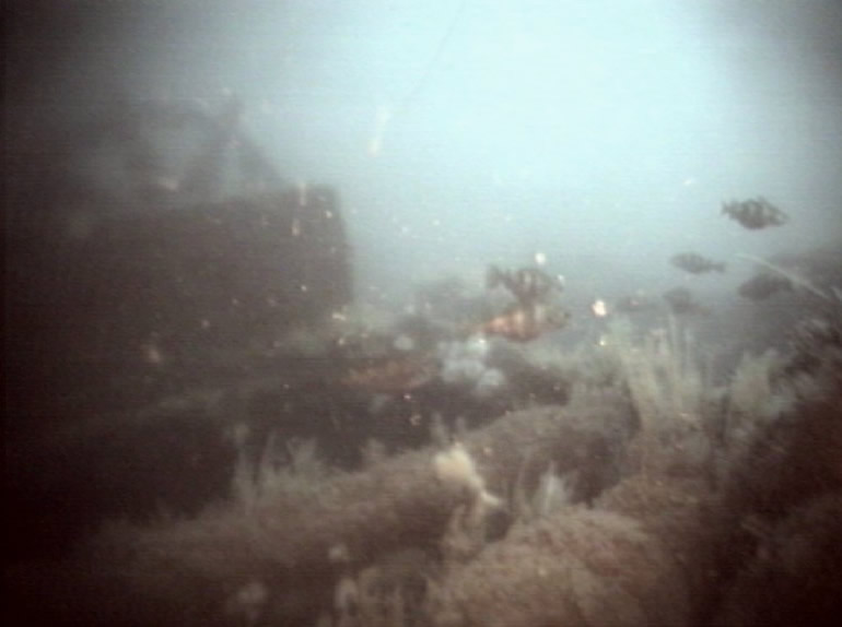
The aft part of the vessel from the rudder at the stern to the two scotch boilers in the engine room is the best preserved section of the vessel. Internal framing and outer hull plating survive to a level of 2-3m above the seabed.
The intact propeller tunnel runs from the 3m high steam engine to the stern. Engine and boilers are well preserved. Forward of the engine room the upper deck has collapsed onto the hull of the vessel with fittings and machinery still attached in their original positions.
The vessel sides have collapsed outwards and are now lying facing upwards on the seabed. In some areas portholes are still visible in the sides. The bow is heavily damaged and not recognisable. The bow area is covered in metal debris. Sand levels in the bow and midship area are high and parts of the wreck in these areas are partially or fully buried. Debris scatters were observed on both sides of the vessel and in the bow area. Little debris was seen around the stern.
Fittings and Machinery
Even though the upper deck of wreck 5009 has collapsed, machinery and fittings are fairly well preserved. Two anchors with folding stocks, probably a large and small kedge, were observed next to the forward edge of the fore cargo hatch on the upper deck. Both are common anchors with iron folding stocks. They are stored with the stocks folded down, the smaller anchor on top of the larger one.
Parts of an anchor windlass were noted beneath metal debris in the bow area of the vessel. Close to the anchors, 1m long bitts marked the side of the vessel (view image). A wire reel with concreted wire was observed on the seabed between the bitts and anchors (view image).
Aft of the fore cargo hatch and the mast partner plate (view image) a steam winch is fastened in the centre of the upper deck. It is well preserved but covered in marine growth (image 1, 2).
A second, slightly larger steam cargo winch is situated 4m further aft. The winch is partly buried and heavily overgrown, but seems to be well preserved.
A third winch has collapsed onto the tunnel in the stern of the vessel. It is lying upside down, covered by its baseplate and could not be recorded other than photographically (view image).
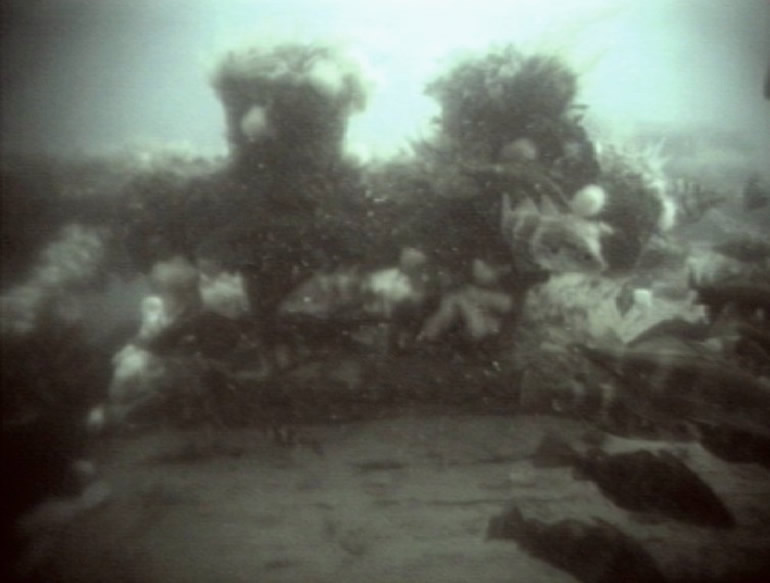
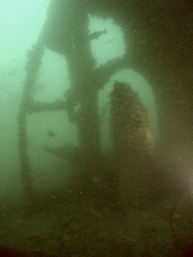
Two scotch boilers and the two cylinder steam engine are the main components preserved in the engine room area. The boilers are 3m long and have a diameter of 3m. The boiler fronts are partially covered with debris and sediment, but stay nuts and fire tubes can be recognised (view image). The boiler shells are made from riveted iron plates. A steam drum with safety valve is attached on top of the starboard boiler (view image). The steam drum on the port side boiler is missing, but the two attachment holes can clearly be seen (view image). A lifting arrangement with lifting eyes and strops was observed on the portside boiler.
A number of pipes have collapsed around and between the two boilers. Some of those probably connected the boilers to the engine. The two cylinder steam engine is well preserved but covered in debris and heavily overgrown. The engine casing is 3.2m long and 1.3m wide. The diameter of the HP cylinder is 1.1m; the LP cylinder is 1.3m in diameter.
A feature connected to the engine on the port side is thought to be the condenser. It is approximately 2m high and 1.3m in diameter (image 1, 2). The whole engine room area is covered in debris. A number of hatches were observed among pipes and unrecognisable metal objects. A pump was seen on the starboard side of the engine (view image). Aft of the engine, the propeller shaft disappears in the tunnel.
The main propeller is still attached at the stern. It has four blades, each 1.45m long and 77cm wide at the widest point. The boss has a diameter of 36cm. A spare propeller is located between the two cargo winches. It is partially buried, but one of the blades could be recorded. The blade is 1.39m long and 80cm wide at the widest point. The rudder is still attached to the sternpost of the vessel. The internal plating has corroded away, but the rudder frame and attachment are intact. The lower part of the rudder is buried in sediment (view image).
What is the 1906?
The Shipwreck Index of the British Isles and the Board of Trade Wreck Returns record that a vessel was lost at this position in 1906. Only one vessel with approximately the same dimensions has been identified in the Lloyds Register; the Swedish steamer Talis. It seems likely that the 1906 Wreck is the wreck of the Talis.
The Talis was built as the Dudley by F & W Smith in North Shields in 1865 as an iron screw steamer of 870t gross. In 1870 the Dudley received a two cylinder compound engine. In 1871 she was lengthened to measure 66.42m x 8.59m x 4.63m. The vessel received new boilers in 1878. In 1885 the Dudley was the first ship bought by Walter Runciman, a young entrepreneur who founded the Runciman Co. and the South Shields S.S. Co. She had been laid up on the Tyne when Runciman found her. The fairly old and small steamer was mainly used in the home trades between Trondheim in Norway and Ipswich on the east coast.
Shortly before her sinking the Dudley was bought by Ångfartygs Aktiebolaget Göteborg and renamed Talis. She sank in a collision with the Liverpool steamship Roman on the 22 July 1906 when en route from Llanelli in south Wales to Gävle in Sweden with a cargo of coal.
Based on diver observations, geophysical data and documentary sources a reconstruction of the Talis as she would have looked in 1906 has been attempted. The vessel had a very short forecastle (5.79m). No.1 hold was situated between the mainmast and the forecastle. Two steam cargo winches were fastened on the upper deck aft of the mainmast between the two fore cargo holds. The 14.32m long bridge deck was located just forward of the engine room. Another steam winch and thus possibly another mast were located on the 17.67m long poop. The existence of an aft hold is very likely. Walter Runciman was one of the first ship owners to abolish square yards and sails on his ships. Because of this the Talis is depicted with short masts and without sails.
Site 5013 The Bottle Wreck
Location
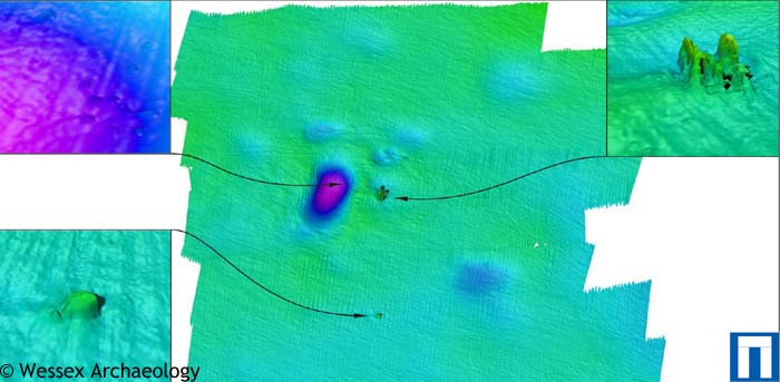
Wreck site 5013 lies 7.18 nautical miles east south east of Selsey Bill. The wreck position is 50.40.919 N, 00.36.557W (Geodetic co-ordinates, WGS 84) or E 668864.22, N 5617198.10 (UTM Zone 30N, WGS 84). The wreck lies in a general depth of 19.7m (CD). Depths experienced on site ranged from 22m to 26m.
What is left on the seabed?
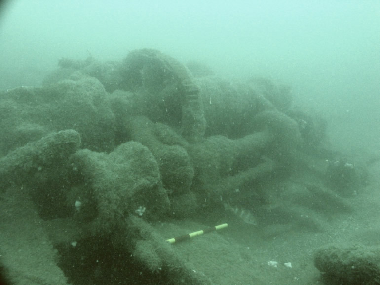
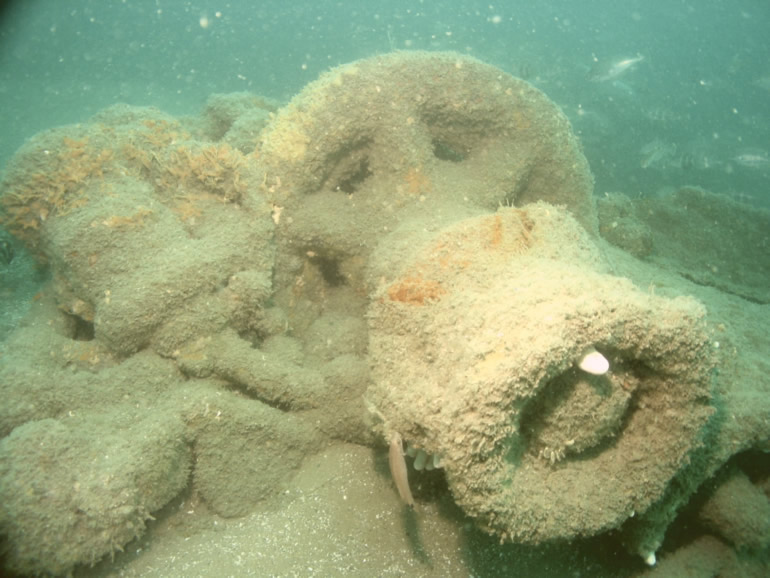
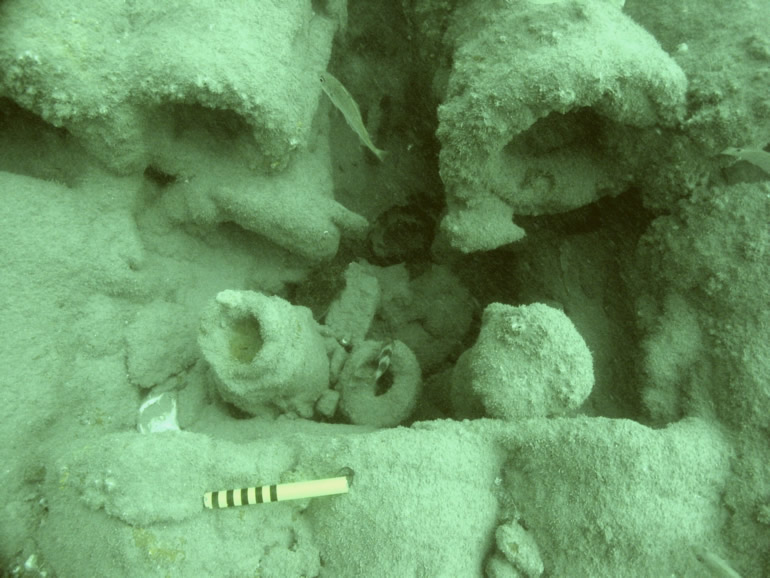
 The wreck is lying on an even keel with a slight list to port orientated NNE - SSW. The site is 28m long and 8m wide. The most prominent feature on the seabed is the cargo of stacked iron pipes which ranges from 60cm to 2m in height. The pipe cargo mound is 11.5m long and measures 6m across.
In an area 4m to the South of the pipe cargo, partly exposed hull timbers mark the location of the bow. To the North buried timber and copper bolts are visible in a distance of up to 10m from the cargo mound. The pipe cargo mound has partly collapsed to the starboard side, where broken pipes and metal debris are lying on the seabed.
Scattered artefacts and concretions are exposed on the seabed in an area of c. 30m around the wreck. A concentration of glass beer bottles and bottle shards was observed in the bow area. North of the cargo mound the seabed is littered with broken pottery and potsherds. Two large irregular shaped lumps of a brown, possibly organic material were observed in the bow area, covering some of the exposed hull structure. The nature of this material is unknown.
Construction
The lower part of the vessel’s hull survives in the seabed. Timbers are exposed in the bow area and close to the stern only. Due to the level of burial, excavation would be necessary to allow more detailed recording of the structural remains.
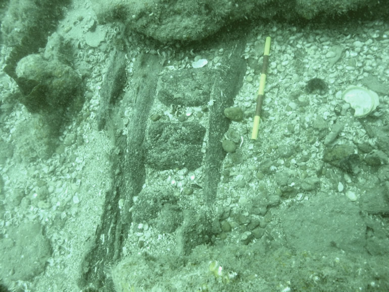
The vessel seems to be built from oak. Outer Planks and ceiling planks are fastened by a combination of trenails and copper drift or clench bolts. In the bow area frames are 16cm to 19cm sided and 18cm moulded. Outer planks are 6-8cm thick and ceiling planks have a thickness of 5cm. In one area the width of a ceiling plank could be measured as 30cm. All trenails have a diameter of 3.2cm. The average diameter of the copper bolts is 2.5cm.
The outer hull is copper sheathed. Small pieces of copper sheathing were found around the wreck and copper sheathing was still attached to an outer plank in the northeast of the site . In the bow area cant frames curve inwards towards the stem post, but the exact position of the post cannot be determined due to the sediment levels on the site.
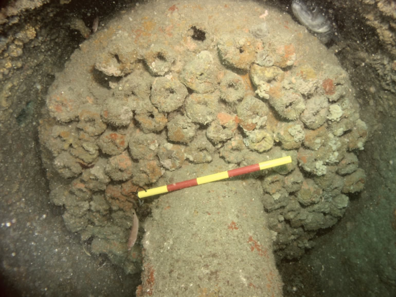
During an excavation of the bow area in 1983, divers of the Chelmsford Underwater Archaeological Unit uncovered the keelson (the upper part of the keel), which was 25cm wide and 23cm high. Just south of the pipe cargo, a mortise measuring 15cm x 15cm was observed in either the keelson or a 5cm high mast step on top of the keelson. The foot of the fore mast would have been stepped into the mortise. The mast step was covered by a round concretion 61cm high and 35cm in diameter, possibly the remains of the fore mast.
A second mast step, covered by concretion, was observed just forward of a pump box in the pipe cargo mound in 2005. Measurements could not be obtained as the pipes shifted sternwards onto the pump box and covered the mast step. Its association with the ship's pumps would suggest that this was the position of the main mast.
At the stern a single timber was seen 8m aft of the pipe cargo mound in line with the lubber line of the vessel. It is heavily eroded and measures 2m by 50cm. Three eroded copper bolts extend upwards from the timber. Judging by its location, this could be part of keel, keelson or part of the stern construction of the vessel.
Fittings
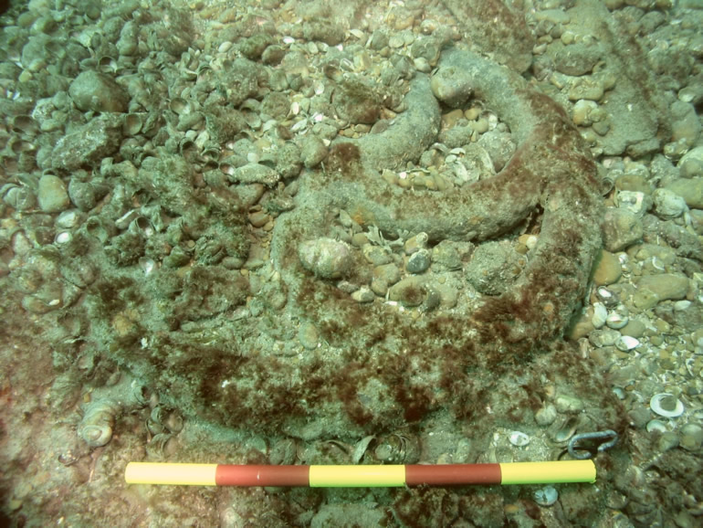
 Very few fittings are preserved on the seabed. The shaft, stock and ring of a small anchor were observed in the bow area on the portside of the vessel. The iron stock is 4cm in diameter and 1.3m long. The ring has an outer diameter of 20cm. The inner diameter is 12cm. The shaft is heavily concreted and barely visible. Crown and arms are buried.
An iron pump box, measuring 1m x 40cm is located aft of the mainmast in the pipe cargo mound. The concreted remains of two metal suction pipes, each of 18cm diameter are visible in the box.
Cargo
Several different types of cargo are known to derive from site 5013. The cargo can be divided into the following categories:
-
Cast iron pipes
-
Beer (in barrels and bottles)
-
General Cargo (including pottery, cutlery, razors and guns)
Cast iron pipes
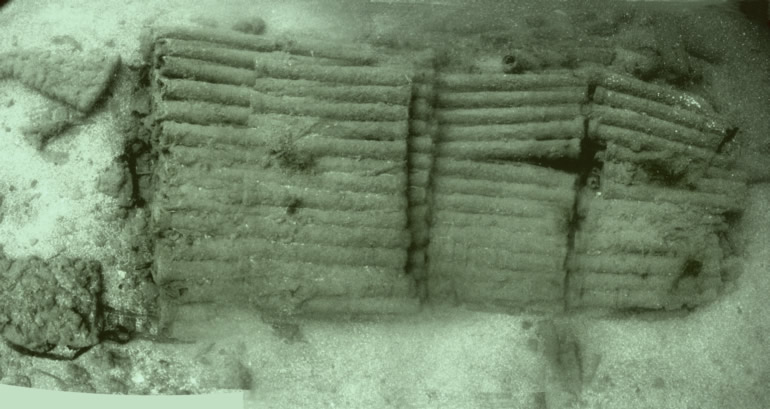
Lengths or 'sticks' of cast iron pipes form the main cargo mound which is clearly visible on the seabed. In 1983 divers counted 204 pipes in four banks. The sticks are 2.77m (9ft) long with a 10cm (4in) socket at one end. The external socket diameter is 38cm (15in). External pipe diameter is 30cm (12in). The internal diameter is between 17cm and 18cm (7in).
Type and diameter of the pipe sticks suggests that they were designed as water or drainage pipes. Cast iron water pipes were first used in the late 17th century and became increasingly popular in England and the United States from the beginning of the 19th century. In the United States cast iron pipe production started in 1819. Before this date and to a certain degree even afterwards, cast iron pipe was imported from England or Scotland.
The spigot and socket type pipe joint was developed by Sir Thomas Simpson in 1785. This joint is typical for cast iron water pipes. The pipe sticks were pushed together, and the joints were caulked with lead.
The Encyclopaedia for Municipal and Sanitary Engineering lists typical drainage pipe diameters with associated metal thickness and pipe weight. Water pipes are usually measured by the outer diameter. According to the Encyclopaedia, the 12in pipes found on site 5013 would have been made from 9/16in or 1.4cm thick metal. A pipe stick would have weighed 8.5cwt or 431kg.
Beer
Beer bottles and barrels were found forward of the pipe cargo mound. At least two barrels were excavated in 1983. The barrel staves are 1.07m (42in) long and the words 'BARCLAY & PERKINS' are burnt into the lids of the barrels. The barrels were probably hogsheads and would have contained 54 gallons of ale or porter. The Barclay & Perkins brewery was founded in Southwark, London in 1781 and was the biggest producer and exporter of beer in the 19th century.
Broken beer bottles are scattered on the seabed all around the bow area, forward of the pipe cargo. In 1983 around 500 complete and corked bottles were lifted from the site. The bottles are all of the typical 'porter' shape, common between 1760 and 1918. They are ½ pint in size. Some of the bottle corks were inscribed 'Kinnley Williams London'. Brewers of this name could not yet be tracked down. The bottles contained porter, which was a very dark and malty type of ale based on roasted malt. Porter became popular at the beginning of the 18th century and was known as a working class beer. English porter was exported to a number of countries, among others the United States, Australia and India.
Samples of yeast preserved in some of the corked bottles lifted from the site were used to recreate the original beer in 1991. The result is sold as Flag Porter by the Darwin Brewery, UK.
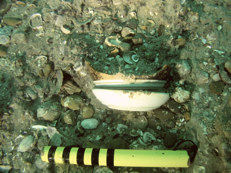
Pottery
The pottery on site 5013 is concentrated in the area aft of the pipe cargo mound. Five different types of pottery can be distinguished:
-
Blue and white transfer printed willow pattern plates
-
Pink, blue and black transfer printed ware, unknown pattern with romantic landscape
-
Dark brown transfer printed ware, Bombay Japan pattern
-
Annular ware, mocha pattern
-
Refined whiteware, plain
Several blue and white transfer printed willow pattern plates were found on the site. Some examples are also kept in Littlehampton Museum. One plate was lifted, photographed and drawn in 2005. The plate has a diameter of 24.5cm and the bottom is marked 'R&C'. This trade mark could be identified as belonging to the pottery Read & Clementson which was based in Hanley, Staffordshire between 1833 and 1835.
Cutlery
In the 1980s unknown quantities of cutlery including spoons, knives and forks were lifted from the site. No complete examples of the knives or forks could be recorded, but a number of spoons and bone knife handles are preserved in Littlehampton Museum. The spoons are of the fiddle pattern, typical of the early 19th century.
Further General Cargo
Further general cargo found on the site includes gun flints and flintlocks, glass salt cellars, silver sugar tongs and a number of cutthroat razors. The bone razor handles were engraved with a number of different motives, including portraits of George Washington, the Liberty Bell and rural farming scenes. A razor handle recorded in Littlehampton Museum was engraved with a horizontal wave pattern.
What is the pipe wreck?
The archaeological evidence gathered during the 2005 field session indicates that wreck 5013 is the remains of a wooden merchant sailing vessel. Judging by the extent of the site and the preserved hull timbers, the vessel was ca. 28m (91.8ft) long and had a breadth of 7-8m (23ft-26ft).
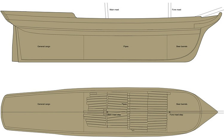
It had at least two, possibly three masts. The foremast was situated 4m aft of the stem post. The distance between foremast and mainmast was 9m. The ship was carvel built from oak and fastened with trenails and copper alloy bolts. The outer hull was copper sheathed.
The ship's bilge pumps, situated aft of the main mast had cast iron tubes. The vessel was carrying a cargo of cast iron pipes, beer and general goods, including pottery. All elements of the cargo date to the first half of the 19th century.
The identification of the maker of one of the blue and white transfer printed willow pattern plates allows more accurate dating, as the pottery Read & Clementson only existed between 1833 and 1835. The terminus post quem for the sinking of the vessel is thus 1833. The terminus ante quem could tentatively be defined as 1835, but there is a possibility that Read & Clementson transfer printed ware continued to be traded after the pottery closed down.
Wreck 5013 was a wooden merchant vessel with at least two masts. The dimensions of 28m x 7/8m or 91.8ft x 23-26ft would be typical for a brig of 200t to 300t.
The copper sheathing indicates that 5013 was intended for trading in warmer waters, either the Mediterranean or the overseas trade. This interpretation is supported by the cargo assemblage found on the site.
Cast iron pipes, porter, beer and Staffordshire ceramics would be typical British export goods in the first quarter of the 19th century. Only the ornamented bone razor handles give an indication of the possible destination of the vessel. Designs such as the George Washington portrait and the Liberty Bell would only have been popular in the United States.
Altogether wreck 5013 is probably the remains of an English brig of 200t - 300t, trading overseas, possibly to the United States. The vessel sank after 1833 and possibly before or during 1835, although a later date of sinking cannot be ruled out. The visible structural remains do not allow a more detailed description of the construction.
Methodology results
Based on the results of Round 1 of 'Wrecks on the Seabed', Round 2 aimed to further develop and test methodologies for the assessment, evaluation and recording of wreck sites. The project objectives related to three different subheadings:
-
Infrastructure
-
Remotely operated vehicles and
-
Intrasite survey.
The Round 2, Year 1 fieldwork was divided into a 15 day ROV session followed by two 15 day diving sessions.
Seven study sites were visited during the ROV session. All of these had been subject to geophysical survey, diver investigation or both in Round 1.
Each of these sites were to be recorded to level 2a with the aim to develop methodologies for the use of ROVs in underwater archaeology and to integrate ROV based methods with tracking and recording systems. In addition, the use of ROV survey instead of diver-based methods and the use of ROV survey to complement diver-based methods were to be assessed.
The two diving sessions concentrated on three wreck sites that had been very difficult to access during Round 1 of the project. All three sites were recorded to level 3a or 3b in the course of the diving sessions of Round 2.
Round 1 diving was conducted from a small workboat that returned to port every night. In Round 2, MV Flatholm, a 26m converted tug, was used as the diving support vessel. Weather permitting, Flatholm was able to stay out on site for the whole 15 day session with crew and dive team living aboard.
Infrastructure
When assessing the effectiveness of a larger platform in maintaining station in prevailing conditions it was found that the larger vessel had clear advantages over the small workboat. The position on site could be held in winds up to force 6Bft. When investigating the scope for increasing working time by coping with less favourable conditions, it was found that downtime could be reduced by 10% through the use of a larger vessel. The larger vessel also enabled work on sites that could not be accessed in Round 1.
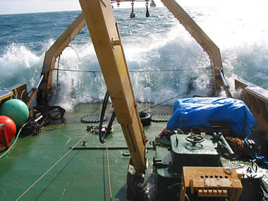
By maintaining station on site whenever possible, travel time was reduced and it became possible to work additional slack water periods. By doing this, the total average bottom time per day could be increased by 60 %.
The larger work platform also proved to be beneficial for the use of acoustic tracking systems, although it was difficult to quantify this effect.
An assessment of the benefits of a larger platform for accommodating and handling diving and ROV systems showed that the larger vessel had several advantages over the small workboat. Equipment could be stored safely, protected from spray and wash. It was also possible to carry out maintenance on board and undertake post-processing tasks, thereby increasing work efficiency.
The use of ROVs in underwater archaeology
It has been possible to develop a methodological approach for level 2a surveys with a remotely operated vehicle. In addition, ROV-based methods were successfully integrated with the USBL tracking system and the Wessex Archaeology diver recording system DIVA.
The use of ROV survey instead of diver-based methods and as a complement to diver-based methods was also assessed.
It was found that when used as a stand-alone tool, the ROV proved to be an efficient mechanism for the rapid survey of large wreck sites with acceptable visibility. The extent and character of wrecks could be determined, and rough site sketches sufficient for a level 2a survey could be made from the tracked ROV video footage in combination with previously obtained geophysical data. However, it was difficult to understand the layout of individual components as the ROV lacked measuring capabilities.
Due to the danger of snagging and losing the vehicle, visibility proved to be an important limiting factor for the use of ROVs on wreck sites.
A comparison of deployment costs showed that a small survey class ROV such as the Seaeye 600 used was slightly cheaper per day than a dive team, and that overall work rate was significantly greater for level 2 survey.
An idealised scenario would be to use the ROV for the level 2a evaluation and then deploy divers for the more detailed level 3, in situ recording. The time consuming tasks of getting an overview of the wreck and defining its extents could be carried out by the ROV and the divers could concentrate on the detailed recording of selected elements identified during the ROV survey.
Intrasite survey
A USBL acoustic positioning system was successfully deployed during diving and ROV sessions. The general positioning accuracy achieved with this system using external sensors in single dives varied between 0.5m and 2m and was sufficient for the tolerances/requirements of a level 2a survey. The issue of low repeatability from dive to dive, attributable to GPS, was avoided by conducting designated positioning dives with the aim of positioning all important elements and datum points on sites in a single dive.
The Wessex Archaeology recording system, DIVA, was improved and upgraded to run with ArcGIS 9 rather than Arcpad and to include new features. Altogether the recording system with its seamless integration with the acoustic positioning system was found to facilitate decision making in the field and greatly reduce post-processing times.
As part of the objective to develop underwater video and still photographic methods, different camera and lighting systems and settings were tested under a variety of conditions to find the best camera and strobe settings.
During the post-processing of photography and video, photo mosaics were derived from digital still photos and video captures. Two different software packages were used. Smoky City Designs Panorama factory was found to work best for panoramic underwater still shots taken by swivelling around a single point. The photomerge function in Adobe Photoshop Elements worked well for stitching video captures into plan view photomosaics.
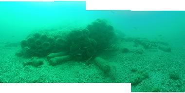
As part of the development of underwater video methods, video editing facilities were used on site. After each dive the captured video was reviewed and important clips were stored in a site movie project. This allowed site sketches to be corrected and completed and effectively reduced post processing times.
As part of the project, the levels of archaeological recording for level 2 and 3 were refined. Recording tasks and related recording foci were added to each of the levels and sublevels.
Altogether the project has improved the knowledge necessary for specifying and conducting rapid and efficient ROV and diver based wreck surveys in areas with conditions similar to the English Channel Coast.
Year two geophysics
The geophysics section of the project was split into two parts. Firstly, an area survey tested different survey specifications over an area of seafloor thought to contain the wreck of the Thomas Lawrence, an 18th Century schooner. Secondly, surveys were made of three charted wrecks sites in deep water.
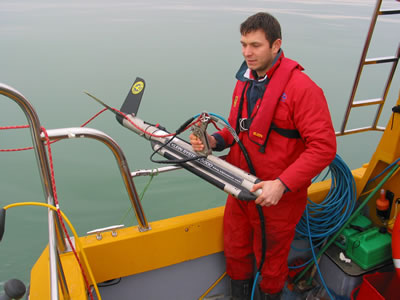
Project background
The aim of Round 2 of Wrecks on the Seabed is to provide industry, regulators and contractors with a framework for a staged approach to the investigation of wreck sites. Such a framework is important when considering the time and cost of marine investigations. It is also helps effective communication between industry, regulators and contractors. The project design for Round 2 of Wrecks on the Seabed builds on the experience of Round 1 of the project.
The project addresses the following aspects of wreck site investigation:
-
A geophysical survey of a 2x2km area of seabed presents an opportunity to develop methodologies for the survey of ephemeral wreck sites.
-
With the dredging industry moving into deeper water, one of the key points emerging from industry is the applicability of wreck investigation methods to greater water depths. The geophysical and Remotely Operated Vehicle survey of three unknown wreck sites in water depths between 46 and 60m will serve as a basis for the development of effective methods for assessing, evaluating and recording wreck sites in deeper water.
-
As most of the problems encountered during the diving fieldwork of Round 1 were related to the size of the diving vessel, a larger Remotely Operated Vehicle / diving support vessel will be deployed in Round 2 of the project. An analysis of the costs and benefits using larger vessels will be carried out.
-
Four of the wreck sites investigated by divers in Round 1 of the project will be revisited with an Remotely Operted Vehicle in Round 2. This will allow a direct comparison of Remotely Operated Vehicle and diver based results.
-
The project results will be made available to the public through web pages, brochures, lectures, conferences and diver information packs for recreational divers.
As the project is specifically tailored to the requirements of marine aggregate dredging, the study areas and sites chosen are all situated close to existing or intended marine aggregate extraction areas.
Objectives
The objectives of the geophysical surveys were divided into two groups;Area Methods and Ephemeral Sites, and Sites in Deeper Water.
Area methods and ephemeral sites
-
Refine and develop methodologies related to area survey methods and the survey of ephemeral sites;
-
Compare and contrast substantial, purposely-collected datasets from relevant and independent survey scenarios;
-
Standardise the approach to reviewing typical geophysical datasets and to discerning whether an acoustic signal is anomalous or not;
-
Inform briefs and specifications for the Levels of Archaeological Recording (i.e. Level 1, especially Level 1b) established in Round 1.
Sites in deeper water
-
Develop and refine methodologies for assessing, evaluating and recording wreck sites in deeper water;
-
Refine the use of geophysical techniques for sites in deeper water and assess the effects on data quality (including positional issues) that may arise from their use in deeper water;
-
Assess the effectiveness of undertaking archaeological recording (to Levels 2 and 3) using Remotely Operated Vehicles (ROV) and geophysical techniques only;
-
Assess environmental issues (e.g. depth, distance from port, fetch) in respect of working on sites in deeper water;
-
Assess infrastructure issues (e.g. anchoring, tow cable handling, and umbilical handling) in respect of working on sites in deeper water.
Methodology
The geophysical surveys for this project were conducted from dedicated survey vessels.
The sidescan sonar and magnetometer surveys over the 2km x 2km area were conducted aboard the survey vessel Titan Explorer operated by Titan Surveys Ltd. The Titan Explorer is a catamaran 9.7m in length and 2.9m in breadth with a draft of 0.6m.
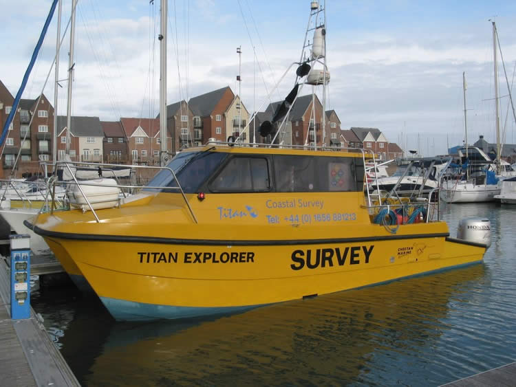
The sidescan sonar and magnetometer surveys of the three wreck sites in deep water were conducted aboard the survey vessel Wessex Explorer operated by Hayes Marine Ltd. This vessel is 15m in length and has a draft of 2m.
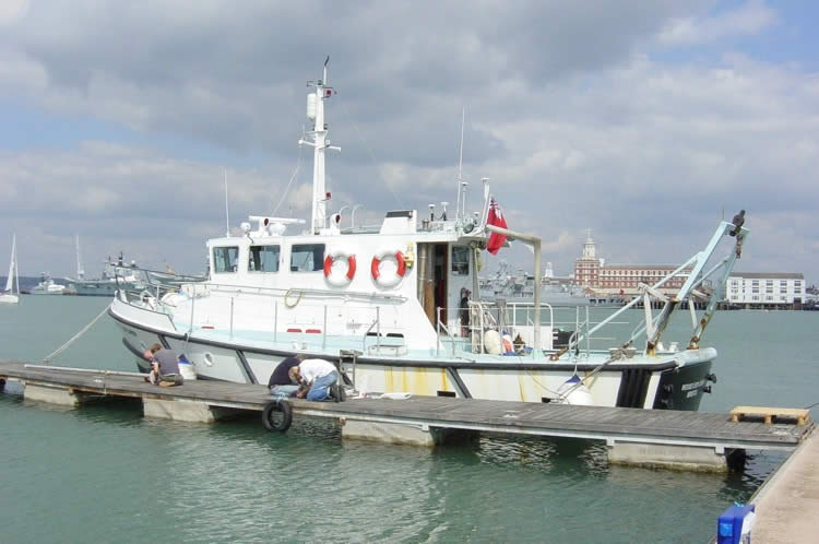
The multibeam echosounder surveys for this project were conducted from the Wessex Explorer.
Sidescan sonar
Sidescan sonars emit narrow beams of acoustic energy from either side of the towfish. This energy is reflected back from the seafloor which produces an image of the seafloor. Hard objects such as metal reflect more energy than soft objects such as sand and mud.
Objects standing up from the seafloor produce an acoustic shadow. On some shipwrecks this can show individual features and parts of the vessels’ superstructure.
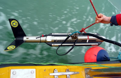
Multibeam
Multibeam sonar surveys ensonify the seabed beneath and to either side of the survey vessel. They record continuous and very accurate spot heights for thousands of points on the seabed as the vessel moves forward.
From multibeam data, 3D terrain models are created. Depressions and features that project from the seabed can be displayed and measured accurately.
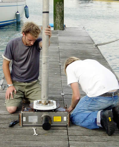
For this project a Reson SeaBat 8125 multibeam echosounder, provided by NetSurvey Limited, was used and the data was processed by Wessex Archaeology using the IVS Fledermaus visualization system.
The results were 3D terrain models, 3D fly through movies and 2D georeferenced images. The 2D images were used as a base for site plans.
Magnetometer
Marine magnetometers detect variations in the Earth's magnetic field. These variations may be caused by the presence of ferrous material such as iron on or under the seabed, geological features or the daily variations in the Earth's magnetic field that are caused by the sun. Marine magnetic surveying is now a standard technique for mapping ferrous material on the seabed.
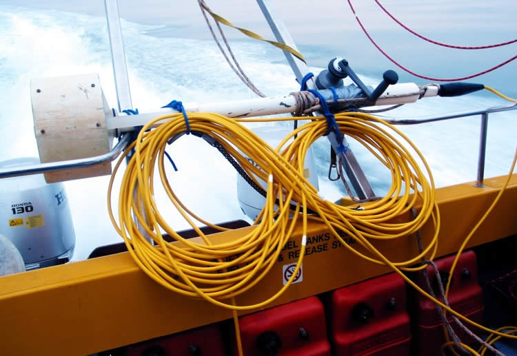
As the survey vessels create a magnetic disturbance themselves, the magnetometer is usually towed behind it.
During the 2005 fieldwork, a Geometrics G-881 caesium vapour magnetometer was used for the 2km x 2km area survey while a Marine Magnetics Explorer was used on the three deep wreck sites.
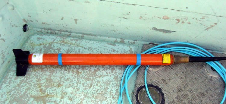
In the post processing the magnetometer data was imported into a Geographical Information Systems (GIS) and overlaid on the results of the sidescan sonar interpretation to compare the results of the two surveys.
Survey Areas and aims
The geophysical surveys were divided into two groups; an area survey of a 2km square, and surveys of three wrecks in deeper water.
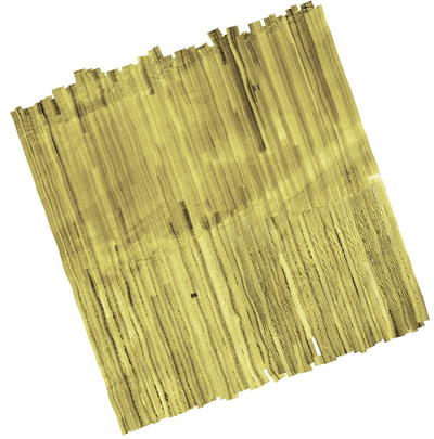
2km x 2km survey area
The 2km x 2km survey area was south of the Hastings Shingle Bank off the Sussex coast in the English Channel. It was chosen because it was thought to contain the wreck of the Thomas Lawrence and it is adjacent to a dredging area. The Thomas Lawrence was an 18th Century Danish schooner which is thought to have been lost in 1862 and was discovered by divers in 1983.
The aim of surveys was to address objectives 1-4 by testing variations in standard survey methodologies. These variations included; line spacing, range setting, and the height of the magnetometer towfish above the seafloor.
The conclusions show how area surveys undertaken by the aggregate industry can best produce data that are suitable the location and identification of ephemeral wreck sites within potential aggregate licence areas using archaeological techniques.
Results
Sidescan sonar data

The sidescan sonar data sets for the 2km x 2km area were divided into eight data sets. This was to show the effect that frequency and range setting have on the ability to detect small or ephemeral sites.
The sidescan sonar used for this project was capable of collecting both high and low frequency data simultaneously. The high frequency setting is able to detect small object and provided detailed images of objects on the seafloor but the energy is not normally capable of getting data at ranges greater than 100m. The low frequency setting is able to provide data out at much larger ranges than the high frequency but at a lower resolution.
The high frequency data set produced the best quality images for the interpretation but only at short range settings (50m or 75m). This is because the high frequency acoustic energy is attenuated before it reaches the end of the longer range settings.
The low frequency data could be transmitted to the end of the 150m range. Although this was suitable for geological interpretation, it was not suitable for detecting the small objects required for archaeological interpretation.
While it was still possible to detect the presence of small objects on both frequencies and at most ranges, only the data sets with high frequency and short range settings allowed the interpretation of whether an anomaly was natural or artificial in origin.
The position of ephemeral sites is also affects whether the sites will be detected, as is shown by the Thomas Lawrence.
Sites like this wreck, with low relief and lying in areas of complex bathymetry, can be difficult to identify as they will not always reflect enough acoustic energy to produce an anomaly. Such sites highlight the need for every anomaly in the data to be recorded and not just those which are identified from more than one survey line.
This means that it is not possible to determine whether an anomaly is a real acoustic signal or noise by simply determining if the anomaly is observed from two adjacent survey lines.
While it has not been possible to develop a system for the automatic discrimination of anomalies in sidescan data as part of this project, it was possible to get an impression of the scale of work that would be involved.
Any such system would have to be able to learn the difference between geological and archaeological anomalies and also discriminate against acoustic noise.
On this basis, it is likely that archaeological assessments of sidescan sonar data are going to continue to be best conducted by experienced geophysicists rather than by software or by people inexperienced with the problems and practicalities of sidescan sonar data.
A final factor highlighted by this survey was that in areas where the sea floor shoals rapidly along a survey line, it is not always possible to keep the towfish at the optimum height above the sea floor.
Where the towfish gets too high, the range is effectively shortened and so the expected data coverage is not achieved. It is advisable that the line spacing is less than the expected minimum range so as to ensure that all areas of the sea floor are surveyed at least twice.
The greatest number of anomalies found in any of the eight sidescan sonar data sets was in the high frequency, 50m range data. All the other data sets had less resolution and so fewer anomalies were identified. This implies that surveys specifically designed for archaeological purposes should use high frequency sidescan systems at low range settings. This project has shown that by using high frequency sidescan sonar systems at either 75m or 100m ranges up to two-thirds of the anomalies within an area may be missed.
At short range setting the low frequency setting did detect slightly less anomalies than the high frequency data set. The main difference between the resolutions of the two data sets was that certain anomalies classified as wrecks in the high frequency data set were described as seafloor disturbances in the low frequency data sets.
The interpretations of different sidescan sonar data sets underline the need for sidescan sonar surveys to be carefully designed so that the correct range and frequency are selected to detect the smallest anomalies expected to be of interest in the survey area. Also the combination of range setting and line spacing needs to be such that at least 220% coverage of the area is achieved so that all areas of the seafloor are ensonifed at least twice, from different orientations.
Magnetic data

The magnetic data was examined in detail to understand the effect of having the magnetometer at different depths in the water column and varying line spacings. This showed that when the magnetometer was kept closer to the seafloor, it detected smaller magnetic anomalies that were not observed when the magnetometer was higher.
This ability to detect smaller magnetic anomalies when the magnetometer is closer to the seafloor was expected. However, there was a difference of less than 10m between the depth of the magnetometer for the shallow and deep data sets but it made a noticeable difference to the number of anomalies that could be identified. This large effect of a small difference in height is noteworthy.
This relationship between the height of the magnetometer above the seafloor and the number of anomalies which it is possible to detect also explains why more anomalies were found in the north of the area than in the south. The magnetometer was kept at a constant depth below the sea surface on any given survey line but the seafloor within this area shoals by up to 23m from south to north, so the magnetometer was closer to the seafloor in the north.
As it may not be possible to alter the depth of the magnetometer during a survey, areas with rapidly changing bathymetry are likely to pose a problem to marine geophysical surveys.
The effect of increasing the line spacings also reduced the number of magnetic anomalies identified, which again was to be anticipated. Small magnetic anomalies will only be detected when the magnetometer passes almost directly over the causative object. Large magnetic anomalies such as the metal wreck outside the SW corner of the survey area produce large magnetic anomalies which can be detected a few hundred metres away from the causative object. Therefore, in order to detect small magnetic fields the closest possible line spacing must be used.
However, a balance needs to be found between practicality and efficiency in magnetometer surveys as it is not always possible to collect large amounts of magnetic data with a narrow line spacing.
Multibeam data
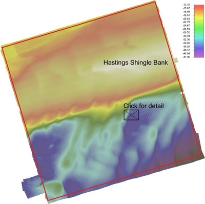
The multibeam data acquired over the 2km x 2km area was not able to detect the Thomas Lawrence or any of the other small or ephemeral sites. This is perhaps surprising given that this data set was collected using the highest possible resolution system available and with archaeological considerations as a primary concern.
Therefore, marine surveys for detecting small or ephemeral sites of archaeological interest are best conducted using a sidescan and magnetometer with the closest line spacing considered to be affordable. The sidescan sonar used should be a high frequency system and the range setting should be as short as possible to still allow at least 200% coverage when run at the line spacing considered to be affordable.
Multibeam surveys do add information to such investigations but it is not advisable to use multibeam systems on their own or as a means for prospecting for archaeological sites. Where they are used, though, then the system should be a high resolution system with the narrowest beamwidth affordable. Also, any wreck sites should be surveyed with the vessel at low speed and the ping rate of the multibeam system as high as possible. The archaeological geophysicist should then review all the data and not just the filtered data produced for hydrographic interpretation.
Thomas Lawrence
The Thomas Lawrence was a Danish, 18th Century schooner, which sank off the south coats of England in 1862. It was discovered by divers in 1983 and subsequently excavated in 1985. Since then the position of the wreck has been unclear and it has proved difficult to re-locate despite a number of attempts. The wreck was reported to be located in the south-western part of the survey area for this stage of the project and initial documentary research provided five possible locations for the site. As part of the area survey Wessex Archaeology found a wreck believed to be the Thomas Lawrence and have been able to provide its precise location.
The wreck was identified from the sidescan sonar datasets during initial processing, though the site was not consistently interpreted as being a wreck. The site was only located on two of the datasets after correlation of all the data in the GIS. Images of the site from each of the sidescan sonar data sets demonstrate the varying quality of the data.
In all, the Thomas Lawrence was identified 21 times out of a possible 36 in the sidescan sonar data with the positions from these sites covering an area approximately 60m (N/S) by 55m (E/W).
The wreck was only positively identified as a wreck or possible wreck site on two of the datasets (500kHz and 100kHz both at 50m range settings) during the initial processing.

Although the site was constantly identified as an anomaly at both high and low frequencies and on all range settings, it was not consistently identified as a wreck. Only the data acquired with the 50m range setting provide sufficient resolution for structures to be identified within the wreck, although these structures are just linear reflectors and not identifiable parts of the wreck.
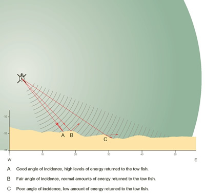
In addition, the nature of the survey pattern should have ensured that the wreck site was surveyed multiple times within each sidescan data set. This was not the case. The reason for this becomes apparent when the position of the Thomas Lawrence is viewed within the context of the surrounding bathymetry. The wreck is located on the side of a large sandwave that may be covering part of the site.
From sidescan sonar survey lines to the west of the site, the acoustic energy striking the Thomas Lawrence would have a low angle of incidence and very little energy would be reflected back to the sidescan towfish. Therefore only sidescan sonar survey lines to the east of the site, which would have a high angle of incidence to the site and consequently a large amount of energy, would be reflected back to the towfish producing good images of the wreck.
The position of the Thomas Lawrence is such that it is also near the base of the Hastings Shingle Bank and so survey lines oriented E-W, and passing to the north of the wreck site, would not have produced a clear sidescan image. This problem, when combined with the fact that the wreck is partially buried and also has no discernable magnetic signature during this survey, have given the Thomas Lawrence it’s reputation for being very difficult to locate.
Deep wrecks survey
The three wrecks in deeper water were selected from United Kingdom Hydrographic Office (UKHO) wreck data for the south coast for the same area studied in Round 1 of the Wrecks on the Seabed Project. The choice was narrowed to wrecks that were unidentified and lying in approximately 50m of water.
The chosen wrecks were:
|
Wessex Archaeology No. |
UKHO Comments |
Depth |
|
1001 |
Small wreck – intact - wooden |
56m |
|
1002 |
Lying on starboard side – masts lie alongside |
49m |
|
1003 |
Intact – probably two masts |
46m |
Standard surveys were conducted over each wreck using a sidescan sonar, magnetometer and multibeam echosounder similar to the surveys conducted in Round 1 of the project.
Site 1001
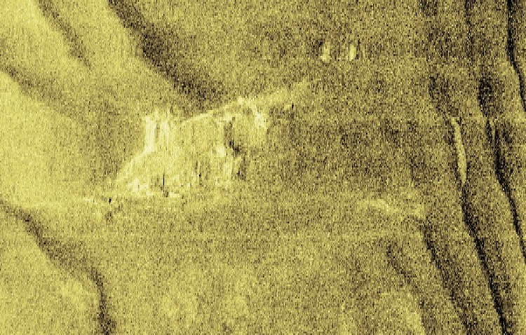
Wreck WA1001 was described by the UKHO as being a small wreck, intact and possibly wooden, at a charted depth of 56m with the surrounding seafloor at only 57m – 58m deep shoaling to 50m to the northwest of the wreck.
The wreck was located during this survey using the sidescan sonar and found to be within 10m of its recorded position.
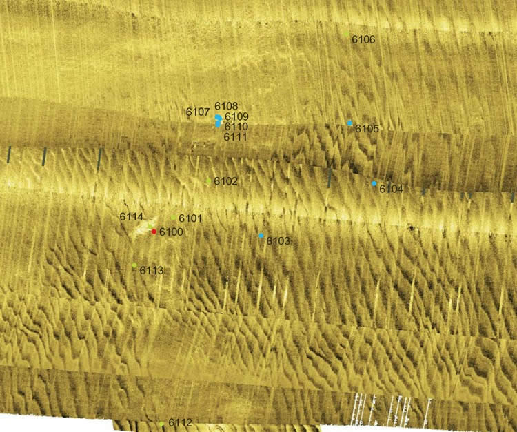
The sidescan sonar data consisted of two prospection lines and nine survey lines each approximately 600m long, orientated E-W with a 75m range setting and covering an area approximately 600m x 330m.
A further three lines orientated N-S were surveyed over the wreck itself. Forty-eight anomalies were identified.
| Archaeological Potential | Number within Study Area |
| High | 1 |
| Medium | 6 |
| Low | 8 |
| Very Low | 0 |
| Archaeological Potential Rating of geophysical anomalies within the WA1001 Study Area |
After the sidescan sonar survey, magnetometer survey lines were acquired with nine survey lines orientated N-S and six survey lines orientated E-W. Two magnetic anomalies were identified.
The 48 sidescan sonar and two magnetic anomalies were then viewed in the GIS and grouped into 15 sites. Each was given a level of Archaeological Potential:
The largest piece of wreckage in this area (WA6100) measured approximately 25m x 10m. It is characterised by an area of reflectors which are brighter than the surrounding seafloor, with evidence of possible structure.
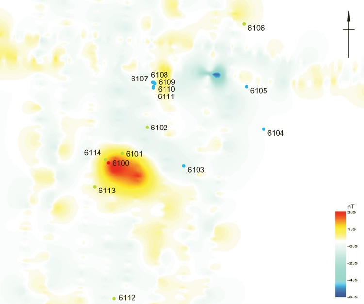
This shows that the material is reflecting less energy than the surrounding sediment. These results are typical of saturated wood lying on sand or gravel. This supports the UKHO record that the wreck is wooden and it is independently confirmed by an associated magnetic anomaly of only 4.82nT.
From 25m to the SW of the wreck site to 50m to the NE there were four sites of medium archaeological potential (WA6101, WA6102, WA6113 and WA6114) which were all likely to be debris associated from the wreck. The largest of the four, WA6102, was not described as debris but as a seafloor disturbance. This may be because it was a large section of partially buried wreck rather than a piece of debris on the surface.
Approximately 180m to the north-east of the wreck is another large piece of wreckage (WA6106) classified as being of medium archaeological potential. It measures approximately 6m x 1m and has a magnetic anomaly of 6.47nT.
The final site of medium archaeological potential (WA6112) is 125m to the south of the wreck and is a large area of bright reflection which may also have been part of the wreck.
We cannot be sure that all six sites of medium archaeological potential and the number of other smaller anomalies scattered over the area all belong to the same wreck.
But if they do, it suggests that, contrary to the UKHO record, the wreck is broken up and covers an area of approximately 300m x 200m.
Of the 15 sites identified within the WA1001 survey area, only 3 have relief of around 1m high in the sidescan sonar data. The majority of the sites lie flat on the seafloor and may be slowly being covered by seafloor sediments.
The multibeam data covers an area of approximately 740m x 540m. The depth of the seafloor ranges from 49m to 58m. As with all multibeam systems, the resolution of the data is a function of water depth and the beamwidth of the system. The Reson 8125 used for this project has a beamwidth of 0.5° and therefore the footprint of the beams over this site was approximately 0.7m.
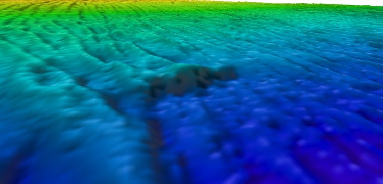
The main wreck site (WA6100) was located within the multibeam data only a few metres from the position determined by the sidescan sonar data. The multibeam data shows that this section is approximately 23m x 7m; slightly smaller than the measurements from the sidescan data.
The multibeam data also shows that the wreck is standing 0.6m proud of the seafloor. This was not observed from the sidescan sonar data.
Viewing the raw soundings rather than the gridded surface provided no further information about the wreck.
The area is covered by sandwaves that are orientated NW-SE. This implies that the main direction of the currents is perpendicular to this. Immediately to the SE of the wreck is a small scour pit approximately 1m deep, which was not detected in the sidescan sonar data.
Site 1002
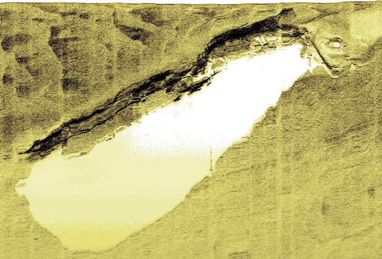
Wreck WA1002 was described by the UKHO as lying on its starboard side, with its bow to the southwest and mast lying alongside the wreck. The charted minimum depth over the site is 49m with the surrounding seafloor 60m deep.
The centre of the wreck was located using the sidescan sonar and found to be approximately 15m NE from its recorded position.
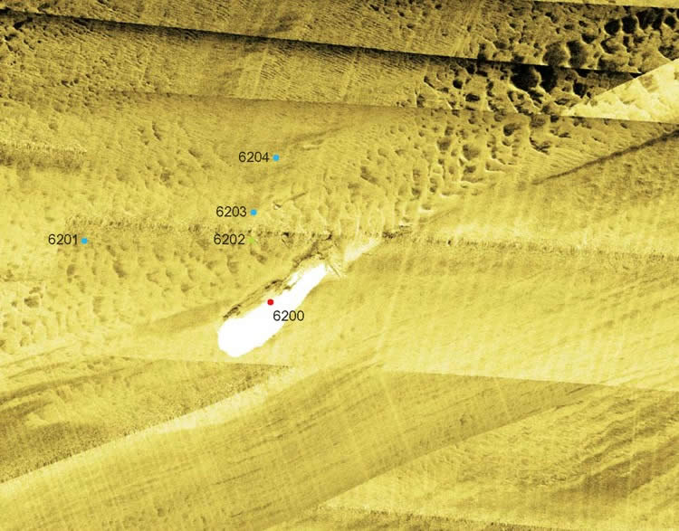
The sidescan sonar data consisted of 11 lines, each approximately 800m long and orientated E-W with a 75m range setting. The area covered was approximately 800m x 350m. A further seven lines orientated NE-SW were surveyed along the length of the wreck. Forty-five sidescan sonar anomalies were identified.
After the sidescan sonar survey, magnetometer survey lines were acquired over the wreck site. The survey lines for this were orientated N-S. One magnetic anomaly was identified.
The 45 sidescan sonar and the magnetic anomalies were viewed in the GIS and grouped into seven sites. Again, each was given a level of Archaeological Potential:
| Archaeological Potential | Number within Study Area |
| High | 1 |
| Medium | 2 |
| Low | 4 |
| Very Low | 0 |
| Archaeological Potential Rating of geophysical anomalies within the WA1002 Study Area |
The wreck is lying one its side in one piece (WA6200) and measures approximately 73m x 7m. It stands up to 7m above the seafloor. While it is difficult to determine which end is the bow, it is thought likely that it is to the south-west which implies that the wreck is lying on its starboard side. This agrees with the UKHO record.
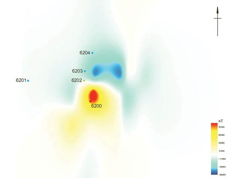
The sidescan sonar data show considerable evidence of structure remaining on the wreck although only one image shows an object that could be the mast recorded as lying alongside the wreck by the UKHO. To the stern of the wreck is a large structure that may be an A-frame and which could be an indication of the type of vessel.
This site (WA6200) has a magnetic anomaly of 1312.49nT, which confirms that the vessel is metal. The size of the magnetic anomaly produced by the wreck obscures any other smaller magnetic anomalies that may lie nearby.
Although wreck WA6200 appears intact, there are six sites around it, one of which is 230m away, which are interpreted as associated debris.
The multibeam data covers an area of approximately 1000m x 460m with the depth ranging from 52m to 60m. The Reson 8125 used for this project has a beamwidth of 0.5° and therefore the footprint of the beams over this site was approximately 0.8m.
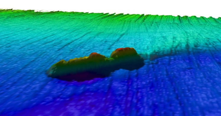
The main wreck site (WA6200) was located within the multibeam data only a few metres from the position as determined using the sidescan sonar data. The multibeam data shows that the wreck is approximately 63m x 10m x 8m.
The width and height are very similar to those recorded in the sidescan sonar survey but there is a large difference between the length measurements. The length of the wreck as measured from the sidescan sonar data ranged from 58m to 73m but the multibeam measurement of 63m is likely to be the most accurate.
From both the sidescan sonar and multibeam data sets, it can clearly be seen that a section of the hull is either damaged or missing from the midships area of the wreck. It is not possible to determine from the geophysical surveys whether the damage was caused at or shortly after the time that the ship sunk or by the deterioration of the hull on the seafloor.
Viewing the raw soundings rather than the gridded surface did not provide any further detail that would help in the identification of the vessel, but it did show that a large amount of sediment had built up against it, covering a large portion of the deck.
Site 1003
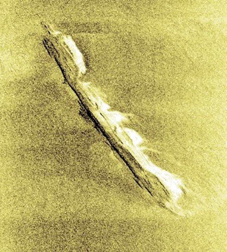
Wreck site WA1003 is described by the UKHO as being intact, possibly with two masts, at a charted depth of 46m with the surrounding seafloor being 55m deep. The wreck was located using the sidescan sonar and found to be approximately 10m due east of its recorded position.
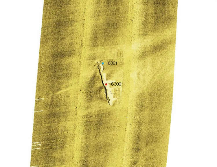
The sidescan sonar data consisted of 11 lines, each approximately 500m long and orientated E-W with a 75m range setting. The survey covered an area of approximately 500m x 350m. A further 19 lines orientated N-S were surveyed along the length of the wreck. Seven sidescan sonar anomalies were identified.
Magnetometer survey lines were also surveyed over the wreck, with lines orientated N-S. A single magnetic anomaly was identified.
The two sidescan sonar and the magnetic anomalies were compared in the GIS and grouped into two sites, both of which ascribed a level of Archaeological Potential:
| Archaeological Potential | Number within Study Area |
| High | 1 |
| Medium | 0 |
| Low | 1 |
| Very Low | 0 |
| Archaeological Potential Rating of geophysical anomalies within the WA1003 Study Area |
The wreck is sitting upright on the seafloor in one piece (WA6300). The sidescan surveys show it to be approximately 81m x 5m, standing up to 2m above the seafloor. While it is difficult to determine which end is the bow, it is thought likely that it lies to the north.

The acoustic shadow produced by the sidescan sonar shows that a significant amount of structure is still present on the deck of the vessel. However, it is not clear exactly what those structures are.
This site (WA6300) has a magnetic anomaly of 2869nT, confirming that this vessel is metallic. The size of the magnetic anomaly produced by this wreck obscures any other smaller magnetic anomalies that may lie nearby.
Although the wreck appears to be intact, one site (WA6301) that lies just 5m away is interpreted as a small piece of associated debris.
The main wreck site (WA6300) was located within the multibeam data only a few metres from the position as determined using the sidescan sonar data. The multibeam data shows that the wreck is approximately 58m x 5m x 3m.
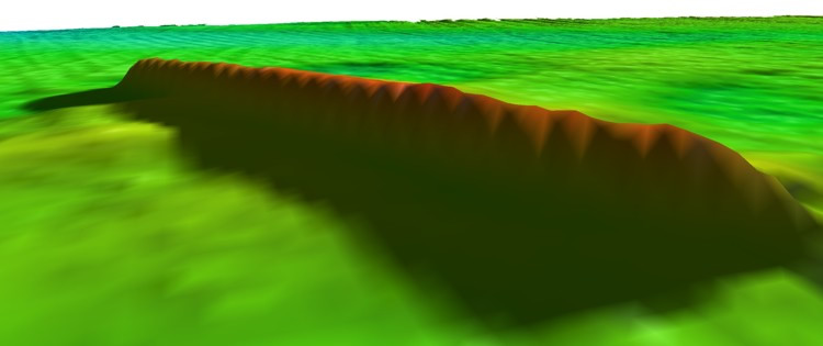
The width and height measurements are very similar to the sidescan sonar measurements but there is a difference between the length measurements. The length of the wreck as measured from the sidescan sonar data ranged from 70m to 87m, all greater than the multibeam measurement of 58m, which is likely to be more accurate.
The differences between the length measurements are due to the different angles at which the wreck has been imaged and the resulting image distortions. The sidescan surveyed it at an oblique angle from different directions while the multibeam surveyed it from above.
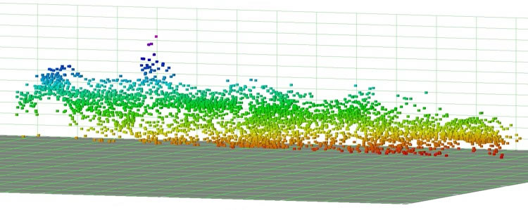
The multibeam survey covered an area of approximately 650m x 450m. The depth of the seafloor ranged from 52m to 58m. The Reson 8125 used for this project has a beamwidth of 0.5° and therefore the footprint of the beams over this site was approximately 0.7m.
Viewing the multibeam data as points rather than as a gridded surface does not provide any more detail on the structures present on the deck of the vessel. It does, though, show that the highest point on the vessel, presumably the bridge, is 45m from the bow.
Year two deep ROV
In 2006 we applied the Remotely Operated Vehicle (ROV) survey methods that we tested on shallow wrecks last year to deep wreck sites. We wanted to find out whether a detailed archaeological survey of a wreck was possible with a ROV.
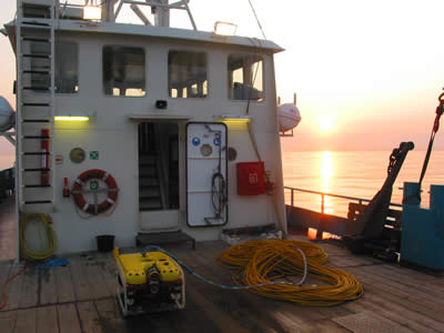
Project background
The aim of Round 2 of Wrecks on the Seabed is to provide industry, regulators and contractors with a framework for a staged approach to the investigation of wreck sites. Such a framework is important when considering the time and cost of marine investigations. It is also helps effective communication between industry, regulators and contractors. The project design for Round 2 of Wrecks on the Seabed builds on the experience of Round 1 of the project.
The project addresses the following aspects of wreck site investigation:
-
A geophysical survey of a 2x2km area of seabed presents an opportunity to develop methodologies for the survey of ephemeral wreck sites.
-
With the dredging industry moving into deeper water, one of the key points emerging from industry is the applicability of wreck investigation methods to greater water depths. The geophysical and Remotely Operated Vehicle survey of three unknown wreck sites in water depths between 46 and 60m will serve as a basis for the development of effective methods for assessing, evaluating and recording wreck sites in deeper water.
-
As most of the problems encountered during the diving fieldwork of Round 1 were related to the size of the diving vessel, a larger Remotely Operated Vehicle / diving support vessel will be deployed in Round 2 of the project. An analysis of the costs and benefits using larger vessels will be carried out.
-
Four of the wreck sites investigated by divers in Round 1 of the project will be revisited with an Remotely Operted Vehicle in Round 2. This will allow a direct comparison of Remotely Operated Vehicle and diver based results.
-
The project results will be made available to the public through web pages, brochures, lectures, conferences and diver information packs for recreational divers.
As the project is specifically tailored to the requirements of marine aggregate dredging, the study areas and sites chosen are all situated close to existing or intended marine aggregate extraction areas.
Aims and objectives
Aggregates being dredged from increasingly deeper waters. As a result, we need to know if the ROV survey methods tested in shallow waters will work on wrecks in up to 60m of water.
Three unexplored wreck sites were chosen to assess ROV methods. The wreckslay in water depths of between 50m and 60m, and had been surveyed with multibeam sonar, sidescan sonar and magnetometer in Round 2, Year One as part of the geophysical section of the current round of the project. The geophysical data from these surveys was used as a basis for the ROV survey.
All three sites were subject to an ROV survey aiming at level 2 or 3 recording.
This report is divided into two parts. Firstly, a methodological section which discusses the individual deep ROV project objectives. Secondly, the archaeological results of the fieldwork are presented.
The aim of the project is to provide industry, regulators and contractors with a framework for the incremental, decision-oriented investigation of wreck sites and with guidance on their archaeological assessment, evaluation and recording.
A framework like this is important when considering the cost and time implications marine archaeological investigations.
It is also important for developing effective communication between industry, regulators and contractors.
Project Objectives
-
Develop and refine methodologies for assessing, evaluating and recording sites in deeper water.
-
Assess the effectiveness of undertaking archaeological recording (to Levels 2 and 3) using ROV and geophysical techniques only.
-
Assess environmental issues (e.g. depth, distance from port, fetch) in respect of working on sites in deeper water.
-
Assess infrastructure issues (e.g. anchoring, tow cable handling, umbilical handling) in respect of working on sites in deeper water.
Methodology
We used the Sara Maatje XV , a survey, supply and support ship operated by Van Stee Survey and Supply B.V. of Harlingen in the Netherlands as our diving support vessel. The vessel has a length overall of 36m, a beam of 7m and a 1m draft.
Sara Maatje XV is equipped with two 300hp main engines, one 500hp Schottel (directional propeller) and a 120hp bowthruster, which provide excellent manoeuvrability.
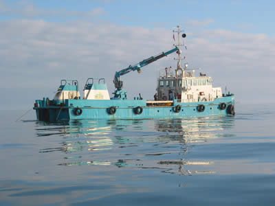
The vessel has a 136m² wood covered working deck equipped with a hydraulic double drum winch for anchoring and a 80t/mtr deck crane.
It provided accommodation for 10 people in five cabins and was equipped with heads, showers, a large messroom and a galley. Water for approximately ten days could be stored in a 13m³ fresh water tank. Three different generators provided 450V AC, 240V AC, 24V DC and 12V DC power supply on board.
The Wessex Archaeology ROV equipment was set up in the large survey office in the wheelhouse.
ROV
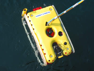
For the survey of the deep wrecks we used a Seaeye Falcon ROV. The ROV and operator were supplied by Subsea Vision Ltd.
The Seaeye Falcon measures 1m x 0.5m x 0.6m and weighs 50kg. Four vectored vertical thrusters and a single horizontal thruster provide a maximum forward speed of more than 3 knots.
The ROV was fitted with a Tritech Typhoon Zoom video camera, a Tritech Tornado Low Light Monochrome video camera and three 75 watt lights.
In addition, a Kongsberg underwater digital stills camera (a Canon Powershot G5 in a Kongsberg housing) with flashgun and a Tritech ISS scaling camera were mounted on an under-slung module for some dives.
The ROV was equipped with forward scanning Tritech Mini King sonar for navigation, a built in fluxgate compass and a digital depth gauge. Information from all these instruments could be displayed over the video output.
The surface controls consisted of the main ROV surface unit, a hand controller with joystick, a screen, two PCs for sonar display and digital stills camera control and a Sony digital video capture unit. Video was recorded on miniDV tapes.
For the wreck surveys we tracked the ROV using an acoustic underwater positioning system.
Acoustic tracking system
An Ultra Short Baseline (USBL) SCOUT acoustic tracking system from Sonardyne was used during all fieldwork sessions to track the Remotely Operated Vehicle and divers.
The SCOUT system consists of three main components: the vessel mounted acoustic transceiver, one or more Remotely Operated Vehicle or diver mounted transponders and the surface command module running the control software.
In a USBL system, the position of subsea targets is calculated by measuring range and bearing from the vessel mounted transceiver to the submerged transponder, which emits acoustic signals.
In a short baseline system, only one transducer (transponder on the seabed) transmits sound, but many transducers on the surface receive signals. In a USBL system such as SCOUT this array of transducers is built into a single transceiver assembly. The baselines between the individual transducers are very (ultra) short, usually in the range of centimetres.
The waterproof and portable surface command module running the SCOUT USBL software was installed in the control room.
The SCOUT USBL Transceiver was mounted on a pole over the side of Flatholm. In order to provide maximum stability for the transceiver the pole had a diameter of 10cm and was attached to a bracket welded onto the rail and supported by another bracket further down the ship’s side. The pole could be swivelled up when Flatholm was in passage.
SCOUT’s very light and rugged Type 7815 HF transponders could easily be attached to either the Remotely Operated Vehicle or diver umbilicals.
The transponder worked on frequencies between 35 and 55kHz. The stated operating range for the system was 500m and the acoustic coverage was +/- 90 degrees below the transceiver.
Even when moored, a vessel yaws, pitches and rolls. As the calculated diver/Remotely Operated Vehicle position is based on the transceiver position, this movement introduces inaccuracies into the positioning and has to be compensated. The SCOUT system allows tracking in two modes: The transceiver includes an internal heading and attitude sensor, which can be used for compensation. Alternatively an external motion reference unit (MRU) and a gyrocompass can be used to compensate for vessel movements.
Using the system on internal sensors is easier, as no external instruments have to be configured, but this decreases the stated accuracy of the system from ± 0.5% of the slant range to ± 2.75% of the slant range.
For both the Remotely Operated Vehicle and diver fieldwork sessions, an external MRU and gyrocompass were installed on the Flatholm.
A TSS HRP-10 MRU was fitted in the survey container. X, Y and Z offset values to the transceiver were entered in the SCOUT software.
An ASG Brown Meridian Surveyor gyrocompass was also installed in the survey container and positioned exactly parallel to the vessel's lubber line.
An onboard GPS provided positioning information. The GPS was a CSI Vector Sensor Differential GPS capable of sub-metre accuracy.
Prior to the fieldwork, all instruments were surveyed on the vessel with the help of a total station by a Wessex Archaeology surveyor to achieve the highest possible positioning accuracy. The offset values to the USBL transceiver were entered into the SCOUT software. All external instruments were connected to the SCOUT surface command module.
Both external and internal sensors had to be calibrated before use. This required the Flatholm to sail predefined patterns around a transponder on the seabed and to steam a full 360 degree circle. A calibration wizard in the SCOUT software automatically applied the necessary corrections to the USBL settings.
Scaling camera
The Tritech Image Scaling System (ISS) can measure the size of objects underwater.
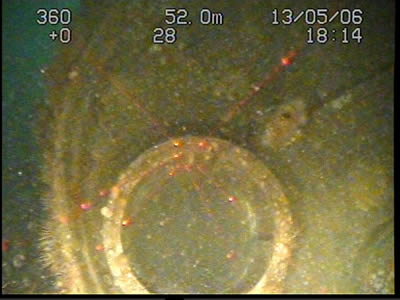
The system consists of a PAL colour zoom video camera with six lasers. Four of these lasers provide parallel beams. The other two are mounted at predefined angles to provide reference points. To measure an object, a video screen capture has to be taken with the lasers pointed at the object. The screen capture is then imported into the ISS-SOFT package after the dive, where the image can be analysed and measurements can be taken Depending on the image quality and camera angle, objects can be measured to within one millimetre.
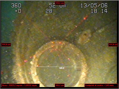
The Wrecks
Site 1001 Unknown B-24
After the geophysical survey of WA 1001 it was targeted for the use of the ROV. Originally thought to be the remains of a wooden shipwreck, the site turned out to be the wreck of a Second World War B-24 bomber. Use the menu above to find out more about this wreck. To see what we found on the wreck site click on the red text or related orange parts in the plan.
The ROV survey of Wreck WA1001 showed that the site had not been correctly identified from the geophysical surveys. The wreck of the B24 bomber was too broken up with not sufficient structure for it to be positively identified as any sort of aircraft. In retrospect this site differed from other wooden wrecks seen by WA in that there was no evidence of isolated planks lying around the wreck site.
Site layout
The geophysical data for site WA 1001 shows two main anomalies. The largest of these which is 25m x 10m. A number of smaller anomalies were detected within of 25m-50m of the main anomaly. Another large anomaly, measuring 6m x 1m lies about 180m to the NE. The resolution of the data is not high enough to discern the exact shape and nature of these anomalies.
As a result of the weather conditions and low underwater visibility, only the main anomaly could be dived in the time available. The low visibility made it very difficult to understand the wreck layout. The wreck plan on this webpage only represents the main anomaly.
The most prominent features on the site are the remains of four aircraft engines which are still attached to the wings or sections of them.
Wing 1 is lying in a NW-SE orientation in the east of the site. The two engines designated Engine 1 and Engine 2 are still attached to the wing and are about 3m apart.
The second wing (Wing 2) appears to be less complete. It lies in a NE-SW orientation about 11m to the west of Wing 1. Engine 3 is still attached to the wing, but Engine 4 could not be positioned accurately.
The fuselage of the plane has broken up but seems to extend in a W-E orientation just north of the wings. Most of the surviving structure is partially or fully buried. What is visible may have been uncovered recently. This is also suggested by the presence of numerous textiles, including American clothing, on and around the site.
No bombs or machine gun ammunition were observed. However, ordnance may be present and the potentially dangerous character of the site should be noted.
No human remains have been sighted during the two ROV dives, but the presence of well preserved clothing on the site makes it very likely some or all of the crew were still aboard the plane when it crashed.
Fittings and machinery
Most of the wreckage is from the aircraft wings. The centre sections of the port wing and starboard wing are fully preserved and lying upside down on the seabed. Most of the wings are still covered with the aluminium outer skin, though this skin is missing along the leading edges.
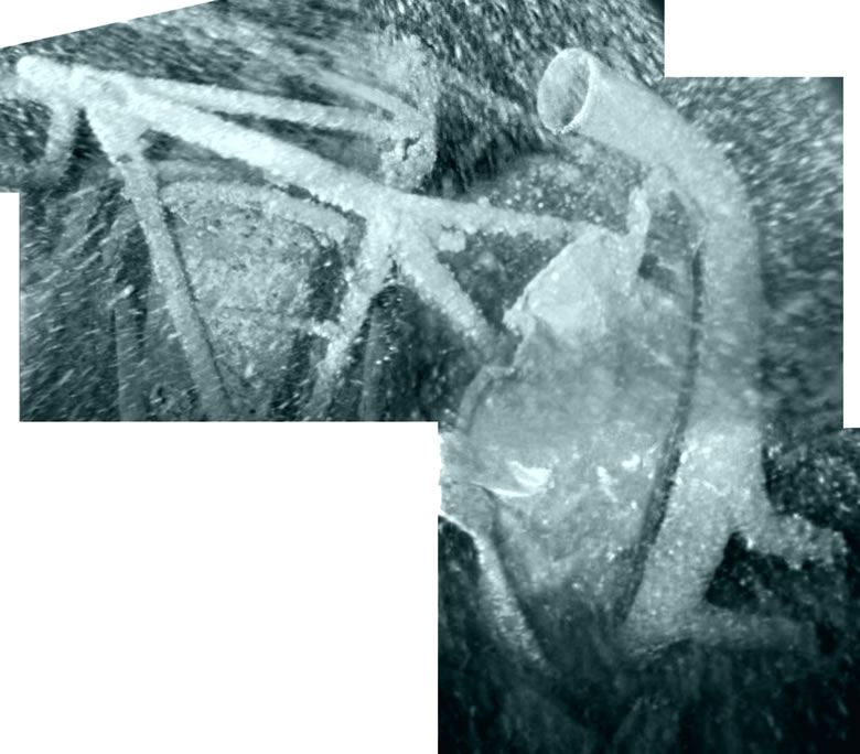
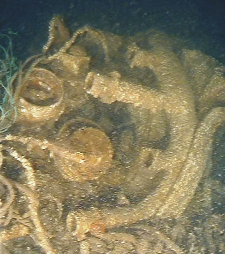
Further wreckage between and to the north of the wing sections could be from the outer wing panels or the fuselage.
The four Pratt & Whitney R-1830 Twin Wasp engines are in situ on the wings though their cowlings are missing. The engine mount assemblies are still attached to the rear of the engines. The inboard and outboard engine mount supports have collapsed onto the underside of the wings.
The engine blocks with their 14 twin row cylinders are surrounded by the exhaust collector rings. The cylinders are 15cm in diameter.
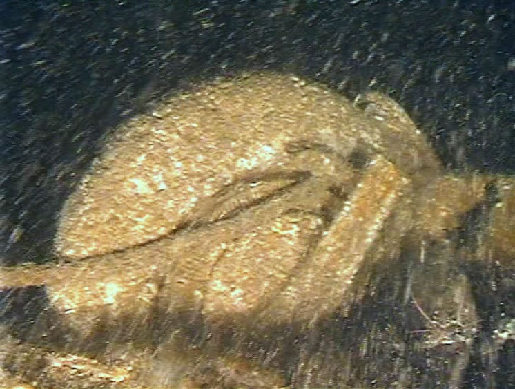
Each of the engines is associated with a rectangular Harrison or Airsearch flattened tube intercooler. The intercoolers serve to cool the hot compressed air delivered by the superchargers.
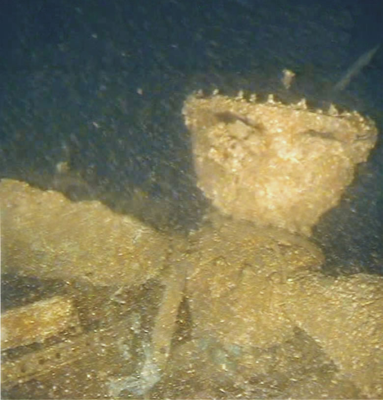
They are situated behind the firewall at the back of each engine. Loose Type B-2 turbosuperchargers were observed on the seabed in the vicinity of Engine 1 and Engine 2. The superchargers were originally located below and at the rear of the engines.
A round oil tank was observed to the east of Engine 1.
Engine 1 and Engine 2 both have hydromatic propellers. On Engine 1, the propeller is lying upside down with the dome buried in the seabed and the nose section facing upwards. The propeller on Engine 2 is lying upright on the seabed south of the engine with the dome facing west and the nose section facing east.
Artefacts
Several pieces of textile were seen in different areas on the site. Some items were half-buried, while others were entangled in and around wreckage. The generally good preservation of the textiles suggests that it was buried until recently.
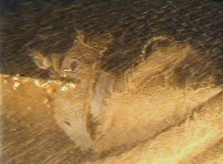
Most of the items on site were difficult to recognise. Strips of olive drab material were observed entangled around fuselage. White fabric, possibly parachute silk was also seen in several areas around the wreckage. A leather strap with buckle attached to olive or khaki fabric was stuck in a piece of aluminium fuselage on Wing 2.
To the west of the wreckage, a thin blue fabric with a white floral pattern lay half buried. This could be the remains of either a shirt or a scarf.
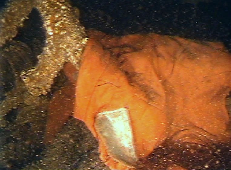
The most diagnostic item on the site was the orange lining of an olive flying parka. This was wrapped around Engine 1. A label attached to the lining is decorated with a floral border and reads “Original Snorkel Parka”.
This type of parka was not a standard military issue item during the Second World War, but looks very similar to the standard issue N-3 snorkel parka that was introduced with the formation of the USAF in 1947.
The N-3 snorkel parka or heavy flying jacket was based on prototypes tested from 1942- 1945. During the war it was common for military personnel to supplement issued clothing with privately bought items. The snorkel parka on the site could either be a test prototype, although the non-military label makes this less likely, or a private item bought by an airman to keep warm at high altitudes in the unpressurised and unheated aircraft.
Identification
Wreck WA 1001 is the remains of a four-engined aircraft, probably from the Second World War. The clothing recorded on the site suggests that the aircraft was American.
The two most common four engine bombers used by the United States Army Airforce (USAAF) during the Second World War were the B-17 Flying Fortress and the B-24 Liberator.
Initial research showed that the B-17 ‘My Day’ of the 388th Bomber Group crashed into the sea off the Isle of Wight in 1943. The 388th Bomber Group Association was therefore contacted to find out more about this accident and possibly identify the wreck.
Some of the ROV video footage was sent to the Curator of the 388th Bomber Group Collection to verify whether the wreck could be the remains of a B-17. After a first review of the footage, it was concluded that the remains on the seabed were not those of a B-17 bomber, but could be from a B-24 or a British four-engined bomber. Further footage was then sent to the 388th Bomber Group Collection and the RAF Museum in Hendon, both of which confirmed that the remains are of a Consolidated B-24 Liberator, lying upside down.
B-24 history
The development of the B-24 long range bomber was started by a request to the Consolidated Aircraft Corporation to set up a second production line for B-17 bombers in 1938.
The Consolidated chief engineer suggested a different design instead, based around a new wing patent that had less drag than the existing B-17 wings.
On 30th March 1939 Consolidated received a contract to build the first prototype of the new bomber which was designated the XB-24.
Development proceeded quickly and a number of the first production models, called YB-24, were delivered to the RAF in 1940. The B-24D was the first mass produced variant of the Consolidated ‘Liberator’ which was used by the USAAF from 1941.
Altogether 2,738 B-24Ds were built. Wartime development then continued through to model B-24M. Most of the later B-24 models were based on the B-24D, with changes in mainly the armament and equipment, as well as attempts to make the bomber lighter in order to increase its performance.
In total, some 19,203 B-24’s of 15 different variants were constructed during the war. Together with the B-17, the B-24 beca me the most used heavy long range bomber of the Second World War.
Technical Specifications
The technical specifications for the B-24D Liberator were:
|
Span |
33.52m |
|
Length |
20.22m |
|
Height |
5.46m |
|
Wing Area |
97.36m² |
|
Weight (empty) |
15413kg |
|
Weight (max take off) |
27216kg |
|
Armament |
One (usually three) 0.5-in (12.7-mm) nose gun, two in dorsal turret, two in tail turret, two in retractable ball turret and two in waist positions; plus a maximum internal bomb load of 8,000 lb (3629 kg) |
|
Powerplant |
Four 1200 hp Pratt & Whitney R-1830-43 Twin Wasp radial piston engines |
|
Max. Speed |
488km/h |
|
Range (5,000lb bomb load) |
1730km |
|
Crew |
10 |
B-24 Liberator bombers in Europe
The first Liberators to enter the European war theatre were the YB-24s, which were also called Mark I models, which were delivered to Britain in March 1941.
These aircraft were used for Atlantic transport duties, and later for long range anti-submarine patrols in the Battle of the Atlantic by RAF Coastal Command. Mark II models delivered later in 1941 were also used by the RAF Bomber Command. The first bombing raids employing Liberator Mark II’s were carried out by RAF squadrons in the Middle East.
After the United States declared war on Germany and Italy on 11th December 1941, the USAAF entered combat on 11 June, 1942 with an attack on the Romanian oilfields at Ploieşti, carried out by 13 B-24 Liberators.
In August 1942 the first strategic bombing raids on Germany were carried out by units of the 8th Airforce from British airfields. The so-called Combined Bomber Offensive, which started in June 1943, involved massive bombing of German occupied areas and plants and factories in Germany by the RAF and the USAAF.
Site 1002 Unknown Steamer
After the geophysical survey of WA 1002, the site was targeted for survey by ROV. The wreck is an unidentified steamer, thought to have sunk during the First World War. Use the menu above to find out more about this wreck. To see what we found on the wreck site click on the red letters or related orange parts in the plan.
The interpretations of Wreck WA1002 from the geophysical and ROV surveys were broadly in agreement with the dimensions of the wreck and the damage to the hull, identified from the geophysics data, were confirmed by the ROV survey. The lack of detail seen in the sidescan sonar data due to the wreck lying on its side could not be compensated for during the ROV survey as conditions prevented the ROV operating on the NW side of the wreck.
Site layout
The wreck is lying on its starboard side with its bow facing SW. The vessel is about 63m long but as the stern area seems to be damaged it could have been longer.
The beam is c. 8-10m and the depth in hold c. 5-6m. The ship does not seem to have broken up. Outlying debris is visible only in an area just off the stern in the NE.
No superstructure is preserved, but the upper deck structure seems intact and a number of deck fittings were observed. The upper deck is vertical and facing NW. At least two cargo hatches are visible. The hull appears to be fairly intact with the exception of a large area of damage on the port side 20m from the stern. Here a 6m x 6m hole was seen in the side of the vessel.
In addition to the possible damage to the stern, the metal at the edge of the hole in the hull is bent inwards, suggesting an impact from the outside.
Due to strong currents and low visibility it was not possible to explore the seabed on the NW side of the shipwreck. The intact upper deck prevented access to the inside of the vessel, so it was not possible to see any internal machinery, cargo, or ballast.
Construction
As most areas were covered by dense marine growth little can be said about the construction of the vessel beyond that it was built from riveted iron or steel plates.
One section of hull plating could be surveyed in more detail. This was fastened by two/three rows of 30mm rivets. It was not possible to obtain measurements of the hull plates themselves, the frames or the beams.
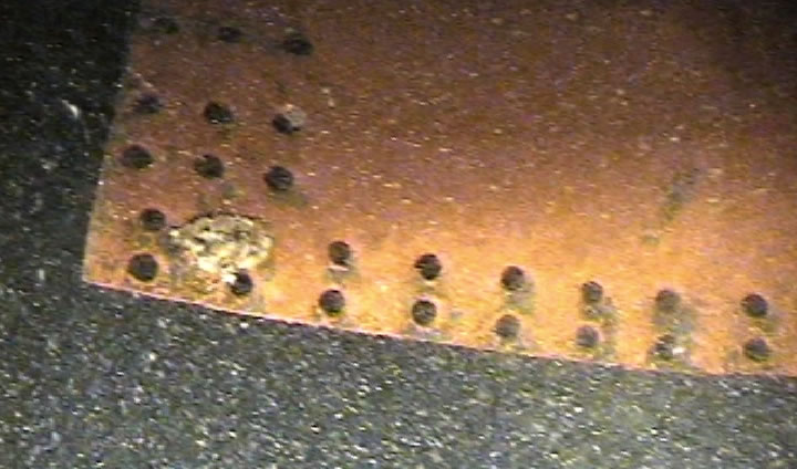
Fittings and machinery
Even though the hull is almost intact, only a few fittings could be observed and recorded on site WA 1002 due to the dense cover of marine growth and the very low visibility.
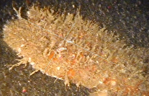
At the bow, a Hall’s patent stockless anchor was observed secured in the hawsehole. One of the anchor flukes was measured with the ISS scaling camera as being 48cm long and 24cm wide. The distance between the flukes is 42cm.
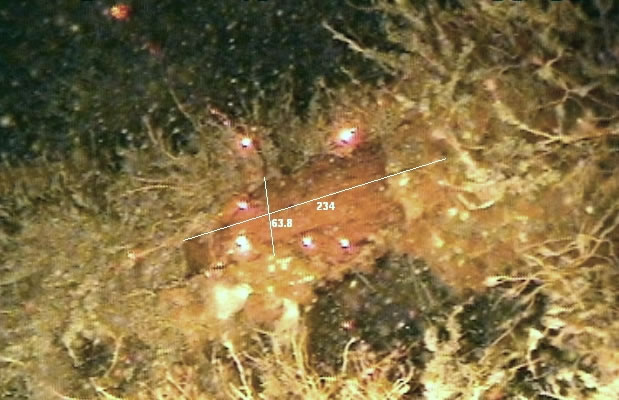
On the now vertical foredeck, an anchor windlass is still secured to the deck. It is heavily concreted but a 6cm wide spur wheel and the 7cm wide brake could be seen. Chain runs from the windlass towards the hawsers. An individual chain link was measured as being 23cm long and 6cm wide.
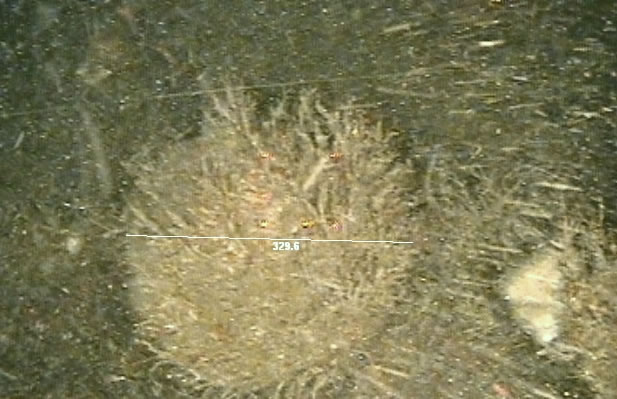 A 5cm wide iron fitting with a block was attached to the side of the foredeck. This could have been part of the rigging or a davit.
Further aft towards midships, two fairleads were observed. Both have an overall length of 65cm and are 22cm wide. The first is situated just aft of the foredeck. The second fairlead is located just aft of midships. It is associated with a set of bollards which measure 32cm across.
Identification
Only limited archaeological evidence could be collected during the survey. However, we know that the wreck is of remains of a riveted iron or steel steam or sailing vessel which was built at the end of the 19th or the beginning of the 20th century. Hall’s patent stockless anchor was first used in 1886.
The general vessel dimensions are: LOA (length over all) 63m, BOA (breadth over all) 8-10m and D (depth in hold) around 5-6m.
Although difficult to determine from the available evidence, the general hull shape suggests a steamship rather than a sailing vessel.
The extensive damage to the hull amidships on the port side suggests how the vessel was lost. The hull is bent inward in this area, suggesting an impact perhaps caused by a shell, torpedo, or a collision with another ship.
Because only limited archaeological evidence is available, the only possible approach to identifying the WA 1002 was to search lists of lost vessels for the general area, such as Richard Larn’s Shipwreck Index. Any vessels that match the dimensions and date of the wreck can then be checked against the United Kingdom Hydrographic Office (UKHO) shipwreck database to see whether they have been identified. Dive guides and the National Monuments Record (NMR) can be also checked.
This process only leaves a few candidates.
The Hall’s patent anchor shows that the ship sank after 1885. As the loss is not recorded, it is seems likely that the vessel sank in either of the two World Wars. In these wars the amount of shipping being sunk made the keeping of accurate records very difficult.
The following vessels have been identified as possible candidates for WA 1002:
|
Vessel Name |
Vessel type |
Vessel dimensions (m) |
Date of sinking |
Recorded Sinking Location/ Position |
|
Peter der Grosse |
Steamship |
LBD 60.65 x 8.65 x 6.33 |
03/ 1893 |
Beachy Head Offshore, not known |
|
Gotthard |
Steamship |
LBD 73.24 x 10.72 x 6.22 |
03.09.1916 |
Beachy Head Offshore, 45nm or 25nm SW |
|
Polpedn |
Steamship |
LBD 78.57 x 11.06 x 5.15 |
14.11.1916 |
Littlehampton Offshore, 20nm S, 50.27.30N, 00.30W |
|
Houlgate |
Steamship |
LBD ?, 929t net |
22.11.1916 |
Beachy Head Offshore, 24nm WSW? |
The Peter der Grosse
The Russian steamship Peter der Grosse sank following a collision with the German Preussen on the way from Hamburg, Germany, to Greenock in Scotland. The vessel was registered in St Petersburg and owned by the St. Petersburg Dampfschiff Gesellschaft (Steamship Company).
The ship was built in Germany in 1872 by the Norddeutsche Schiffbau Aktiengesellschaft in Kiel. The iron steamship was equipped with two boilers and a two cylinder compound steam engine. No further details about the position of the collision with the Preussen could be found.
The Gotthard
The Norwegian steamer Gotthard was torpedoed by UB-25 en route from Middlesbrough, England to Rouen in France with a cargo of cast iron pigs and sulphate. The Gotthard was built in Christiania, Denmark, in 1906. She had a single boiler and a three cylinder triple expansion steam engine.
Two different positions of sinking are recorded for the Gotthard. The English position would put the wreck much further to the South than WA 1002. However, the position given in the Norwegian sources would put the wreck in approximately the right area. The Gotthard is 10m longer than the length of WA 1002 measured on the multibeam data, but this difference could be explained by the apparent damage to the stern area.
The Polpedn
The Polpedn, a steel steamer owned by Farrar, Groves & Co Ltd., London, was sailing in ballast from Dunkirk in France to Ayr, Scotland when she was attacked by UB-38. The vessel was torpedoed amidships on the port side and sank within five minutes.
The Polpedn was an Admiralty prize (ex Thor), equipped with a three cylinder triple expansion steam engine and a single boiler. Although the recorded sinking position is a fair distance from the position of WA 1002, this might be explained by inaccurate positioning due to the rush in which the crew abandoned ship.
As with the Gotthard, a difference in length between the Polpedn and WA 1002 could be due to the damaged stern on WA 1002. The damaged midship section observed on the wreck would be consistent with the torpedo damage sustained by the Polpedn.
The Houlgate
The Houlgate was a Canadian steamer of 929 tons net, owned by a French company at the time of sinking. The vessel was en route from Montreal, Canada to Le Havre, France, with a cargo of coal, when she was shelled by a German submarine.
There are conflicting reports. The crew abandoned ship and watched it sink after an explosion in the boiler room. However, a British patrol ship reported finding the Houlgate deserted the next morning but it sank shortly afterwards. The vessel dimensions are given as 73m x 12m x 4.5m.
It is difficult to narrow down the search any further and securely identify wreck WA 1002 without additional archaeological evidence. All four of the vessels could, in terms of their size and date, be matched with WA 1002 and all are reported to have sunk in the approximate area of WA 1002. In addition, all were subject to damage of some sort, which could be consistent with the damage observed on the wreck.
Site 1003 U-86
After the geophysical survey of WA 1003 the site was targeted for ROV survey. This site, previously listed as unknown, proved to be the wreck of a First World War German U-boat. During the survey it was identified as U-86. Click on red text for photographs of wreck.
The sidescan sonar data for Wreck WA1003 showed a significant amount of detail was present on the wreck. It was not possible to accurately identify what these features were and so the wreck was identified as a large metal hulled vessel. The soundings from the multibeam data identified just one main upstanding feature which was tentatively identified as being the bridge. The ROV survey showed that the geophysics interpretation was incorrect and that the site was a submarine. Using this information it is possible to re-examine the sidescan sonar data and identify many of the features which are now known to be present such as the coning tower and deck gun.
Site layout
The vessel is lying on even keel with a slight list to port on the fairly flat seabed in a NNW-SSE orientation. The bow is in the SSE. The 2005 multibeam survey gives dimensions of 58m x 5m x 3m for the wreck. Dimensions taken off the sidescan data suggest a length of 66m, a breadth of 6.5m and a height off the seabed of 3.5m for the wreck itself.
The outer hull of the vessel has largely disappeared, but the internal pressure hull is fairly intact. The bow and stern are heavily damaged and broken up from the bow bulkhead forward and the stern bulkhead aft. The bow has collapsed and is lying partly buried in line with the vessel. The stern section has broken off and is lying at a 90 degree angle to the main hull, pointing westwards.
Apart from the features associated with the damaged bow and stern sections, outlying debris noted around the site consisted mainly of pressure cylinders that have fallen off the pressure hull. A large seabed scour was noted on the eastern side of the wreck.
Construction
The wreck shows the twin hull construction typical of U-boats: a pressure resistant inner hull and free flooding outer casing.
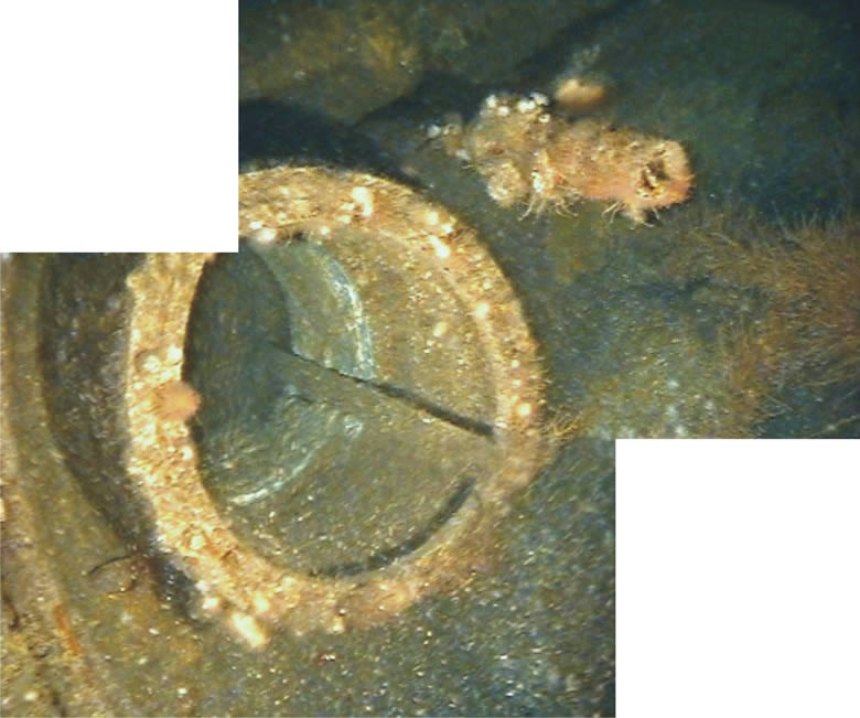
The cylindrical pressure hull is built from riveted 12mm nickel-steel plates with external steel frames. The inside of the pressure hull is separated into compartments by a number of bulkheads made from 16-21mm thick steel. The forward and aft collision bulkheads are visible where bow and stern are damaged.
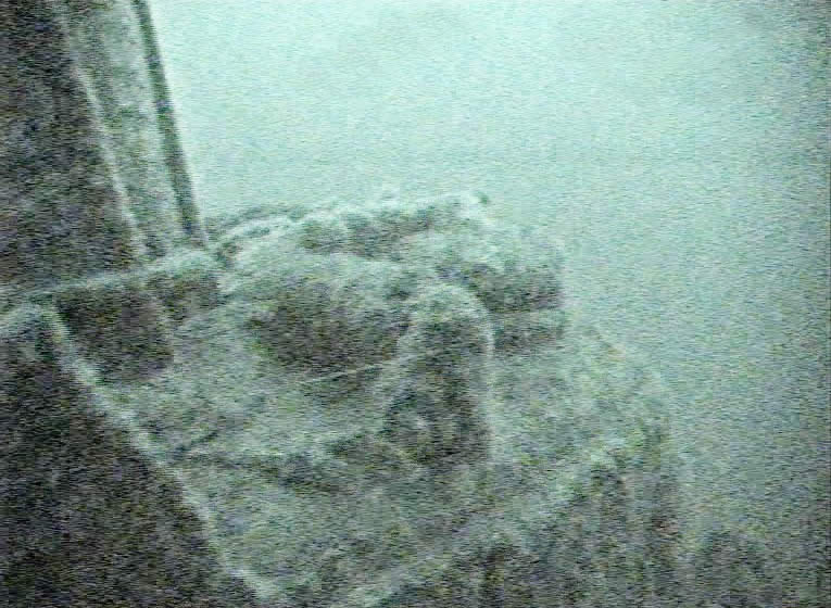
On the outside, the pressure hull is completely surrounded by outer casing made from 3.5-4mm thick galvanised torpedo-boat steel. The outer casing protected the pressure hull. The rigid connection of outer casing and pressure hull enhanced the strength of the pressure hull. On the wreck the outer casing is only partially preserved and the pressure hull is clearly visible in the upper deck area.
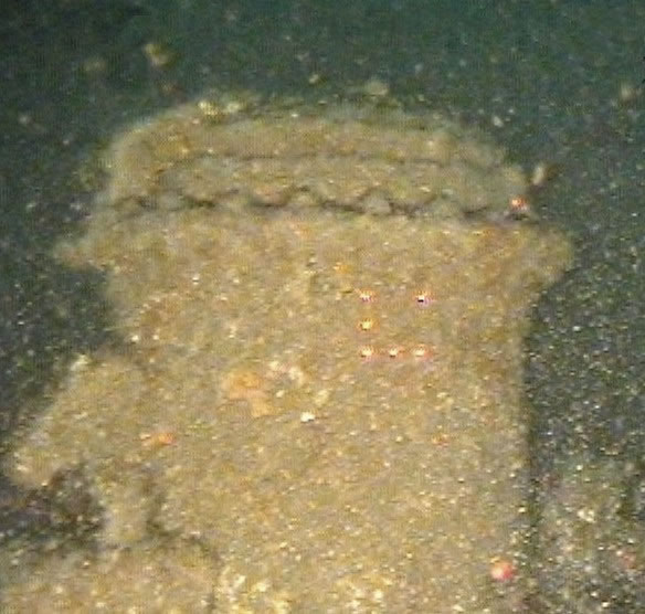
It is made from 30mm galvanised steel riveted onto the pressure hull and is fully preserved with only the protective casing and armour missing. Recesses for the navigation lights and maintenance access hatches are visible either side of the tower. The main conning tower hatch is situated aft of the periscopes and was found slightly ajar.
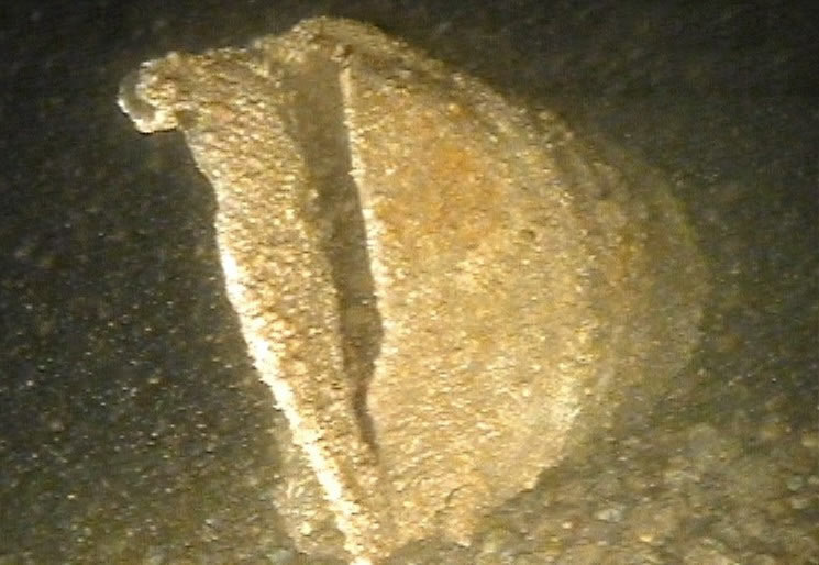
Two torpedo loading hatches were observed at bow and stern, aft and forward of the torpedo rooms. At the stern of the vessel, the engine room escape hatch is wide open. The forward escape hatch is sealed.
At the bow of the u-boat, the two bow torpedo tubes are split at the forward collision bulkhead. The tubes have an internal diameter of ca. 58cm. The tube construction with outer reinforcement rings and bolted segments is clearly visible.
The two stern tubes are heavily damaged and lie at a 90° angle to the hull within the stern wreckage. The outer torpedo tube door is visible on one of the aft tubes.
Fittings and machinery
Most of the fittings that were originally located on the upper deck of the U-boat are in place. The patent anchor is secured in the hawsehole in a recess on the side of the damaged bow section.
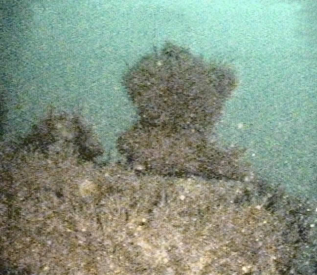
Using the ISS camera, it was possible to obtain some measurements: the anchor shaft is 13cm wide. The anchor fluke measures 24cm x 20cm. The electrical anchor windlass and capstan is in place just aft of the anchor. The opening for the windlass drive shaft can be seen in the collision bulkhead above the two torpedo tubes.
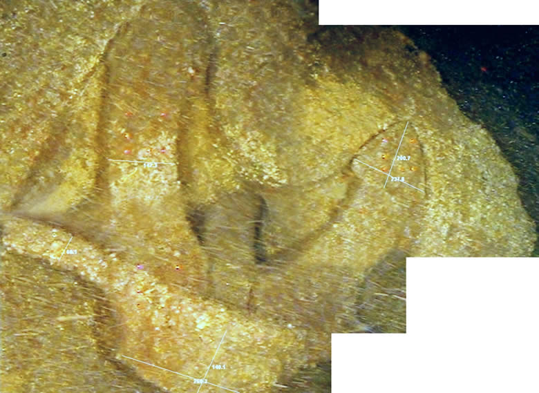
There are a number of compressed air cylinders on top of the pressure hull along the length of the upper deck. These formed part of the boat’s compressed air system which was used to blow air into the dive and ballast tanks. All the cylinders were connected to a compressor in the control room and could be centrally recharged when the U-boat was on the surface. The individual air cylinders are 46cm wide.
The U-boat was armed with two upper deck guns forward and aft of the conning tower. The forward gun is still attached to its mounting and is trained upward. It is well preserved with only a small amount of fishing gear snagged around the barrel.
Due to low visibility and strong currents, it proved difficult to obtain accurate measurements with the ISS camera. However it appears that the calibre of the gun is larger than 10cm. The gun is fitted with a horizontally sliding breech block and top-mounted recoil cylinders.
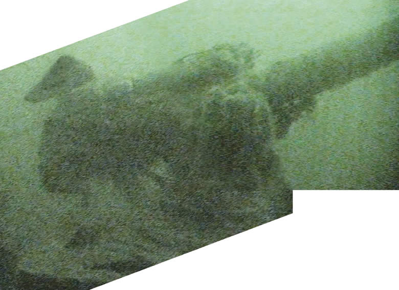
A comparison with small calibre naval guns in use during the First World War shows that it might be a German 10.5cm/45 (4.1") Ubts L/45. This gun was in service from 1907. It was used to arm cruisers, but later in the war it was also fitted on destroyers and submarines. A 10.5cm Ubts L/45 gun from U-98 is preserved in the Imperial War Museum, London.
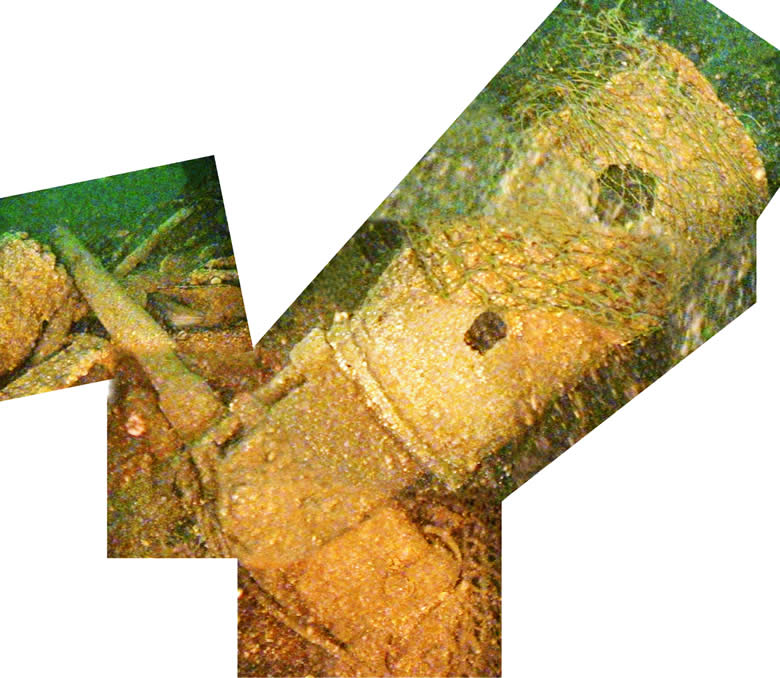
The aft gun is also attached to its mounting but has fallen over to the port side. This gun appears to be the standard World War One U-boat gun, the 8.8 cm/30 (3.46") Ubts L/30. This gun is attached to a circular mounting rather than the collapsible mounting used on some U-boats. The 8.8cm L/30 Schnelladekanone was originally developed for river and coastal gunboats by Krupp in 1898. During the First World War it became standard U-boat armament. An 8.8cm L/30 gun from the wreck of UB-61 is on display in the Bavarian Army Museum in Ingolstadt.

On the conning tower, the mountings for three periscopes are visible. The two main periscope mountings are situated on top of the conning tower, forward of the escape hatch. Both periscopes were operated from the conning tower. The mountings seem to be empty and the periscopes could not be seen. The mounting for the emergency periscope is situated just forward of the conning tower. The emergency periscope was operated from the control room.
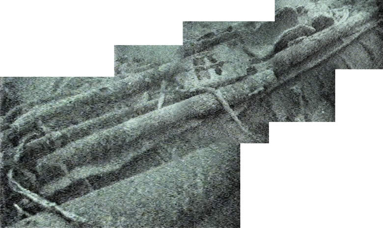
The column for the bridge steering wheel is situated forward of the two main periscopes. The main steering controls were located in the conning tower, but additional steering wheels were situated on the bridge, in the control room and aft in the torpedo room.
The U-boat’s ventilation system has collapsed onto the upper deck and is lying across the hull aft of the conning tower. At the stern the two propellers are still attached to the shafts. The port propeller is missing one of its blades. An intact blade could be measured with the scaling camera. The blade is 75cm long and 40cm wide.
Identification
Wreck WA 1003 is a submarine or U-boat. The vessel is between 58m and 70m long and has a beam of c. 6.5m. The exact length is difficult to determine due to damage to the bow and stern. It stands 3m proud of the seabed, but is partly buried.
The submarine is armed with four torpedo tubes, two bow tubes and two stern tubes. Two deck guns, consistent with guns used on German u-boats during the First World War are visible. No evidence of mine launching chutes could be found.
The size of the vessel, the absence of mine launching equipment and the general layout suggest that WA 1003 is the wreck of an oceangoing German attack U-boat from the First World War.
As a construction and general layout plan of U-63 to U-65 was available during the ROV survey, features observed on the seabed could be compared to this plan.
Apart from a number of details on the conning tower, all fittings and machinery were consistent with the plan. It could thus be concluded that the U-boat was of the so called ‘Ms’, or Mobilmachungs (mobilisation) type.
Ms boats were built by a number of different shipyards and were constantly improved. This led to a variety of subtypes, all with slight variations. Each subtype was named after the first boat built to the specification.
Further study showed that the wreck was consistent with the subtype U-81. This type of U-boat was built at the Germania Werft in Kiel between 1915 and 1916. There were six boats in the U-81 type: U-81 to U-86. Four of them were sunk during the war around Ireland or in the Atlantic. One boat was broken up (uboat.net).
Only U-86 is stated to have sunk or been sunk in the Channel after having been used by the British Navy in 1921. WA 1003 has therefore been identified as the German Ms-type u-boat U-86.
Using archaeological and documentary evidence it is possible to describe the U-86 in some detail.
Technical specifications
U-86 (Construction No 256) was ordered at the Germania shipyard in Kiel on the 23rd June 1915. The keel was laid on November 5th, 1915 and the boat was launched on November 7th 1916.
The technical specification of the boat was:
|
Displacement (m³) surfaced |
808 |
|
Displacement (m³) submerged |
946 |
|
Length (m) |
70.1 |
|
Beam (m) |
6.3 |
|
Draught (m) |
4.0 |
|
Propulsion Main (no. x hp) |
2x 1200 Diesel MAN |
|
Propulsion EL (no. x hp) |
2x 600 EM |
|
Fuel Capacity |
81+38 |
|
Speed surfaced (kn) |
16.8 |
|
Speed submerged (kn) |
9.1 |
|
Range surfaced (nm/kn) |
11200/8 |
|
Range submerged (nm/kn) |
56/5 |
|
Armament |
2 bowtubes, 2 sterntubes, 8 torpedoes (50cm), originally 2 x 8.8cm guns, archaeological evidence for U-86 shows that the bow gun has been replaced by a 10.5cm gun |
U-86 history
U-86 was commissioned on 30 November, 1916 and served until it was surrendered at the end of the War.
It’s first commander was Kapitänleutnant Friedrich Crüsemann, who was in charge of the boat until June 22nd, 1917. On June 23rd Kapitänleutnant Alfred Götze took over as commander. Oberleutnant zur See Helmut Patzig was the last commander of U-86. He was appointed on January 26th, 1918 and served until the boat was surrendered at the end of the war on November 11th, 1918.
Between 1917 and 1918, U-86 was assigned to the 4th U-Flotilla. Altogether the boat conducted 12 patrols. It sank a total of 33 ships (125.580 tons), warships excluded.
In 1918
As an example for the general service of U-86, information for the year 1918 has been extracted from the German naval war diary.
In 1918 U-86 conducted operations in the Skagerrak (the waters between Norway and Denmark), the Irish Sea, the North Sea and the Bristol Channel. It sank the following ships:
-
the British steamer Kafue (6044grt): 1 May, 1918
-
the British steamer Medora (5135grt): 3 May
-
the British steamer Leeds City (4298grt): 7 May
-
the Norwegian steamer San Andres (1656grt): 12 May
-
the British steamer Atlantian (9399 BRT): 26 June
-
the US troop transport Covington (16,339grt):1 July
In June 1918 U-86 was involved in one of the worst war crimes committed by a U-boat commander during the First World War, the sinking of the British hospital ship Llandovery Castle and the subsequent murder of the surviving crew members in the water.
The Llandovery Castle, clearly marked as a hospital ship and known to the German government as such, was en route from England to Halifax, Canada, with nurses, officers and men of the Canadian Medical Corps on board when she was torpedoed by U-86 in the evening of June 27, about 116 nautical miles south-west of Fastnet.
According to witness statements at the later Leipzig war crime trial, the commander of U-86, Oberleutnant zur See Patzig, gave the order to torpedo the Llandovery Castle even though he knew that she was a hospital ship, the sinking of which was illegal under international law and the Hague convention.
Even though the Llandovery Castle sank within ten minutes, a number of boats were lowered successfully and the ship was abandoned in a calm and efficient manner. The lifeboats proceeded to rescue survivors from the water but were interrupted by Patzig, who started interrogating crew members to obtain proof of the misuse of the hospital ship as an ammunition carrier.
When no proof could be obtained, Patzig gave the command ‘Ready for Diving’ and ordered the crew below deck. Only himself, the two accused officers and the boatswain’s mate Meissner stayed on deck.
However, the U-boat did not dive, but started firing at and sinking the life boats in an attempt to kill all the witnesses in order to cover up the incident. To conceal this, Patzig extracted promises of secrecy from the crew, and faked the course of U-86 in the logbook so that nothing would connect U-86 with the sinking of the Llandovery Castle. Of the 258 persons on board only 24 survived.
After the war Patzig fled the country and only the first and second officer of U-86, Dithmar and Boldt could be arrested and tried for their action in the incident.
At the Leipzig trial, both Dithmar and Boldt were sentenced to four years of hard labour. Patzig, with whom the responsibility for the incident rested was never found and prosecuted. Dithmar and Boldt were both released from prison after a few months due to the political changes in Germany.
U-86 was in the first group of u-boats that were handed over to the Allies as part of the armistice treaty at the end of the war. She was taken from Brunsbüttel, Germany to Harwich, England, on November 20th, 1918. From September 1919 to March 1920, U-86 was commissioned into the Royal Navy to test her design and make comparisons with other classes and later designs.
After decommissioning U-86 was scuttled at sea at the end of June 1921. The evidence of the ROV survey suggests that the bow and stern of the U-boat may have been blown off to sink the vessel.
Sources
The following webpages contain material related to U-86:
The plans for U-63 were found on this webpage. The page also contains a wealth of information relating to naval technology of WW1.
www.wlb-stuttgart.de/bfz/marine/index.htm
The naval archive in the Bibliothek für Zeitgeschichte in der Württembergischen Landesbibliothek holds an extensive collection of photographs of U-boats from both World Wars.
U-boat net is probably the most extensive web archive of everything and anything related to U-boats.
www.gwpda.org/naval/lcastl10.htm
This webpage has extensive information on the sinking of the Llandovery Castle.
www.juergenthuro.de/html/8_8_wki.html
Information on the guns on U-86 was extracted from these two webpages.
Methodology results
In summary, the project has shown that Remotely Operated Vehicles (ROV’s) are effective tools for the archaeological survey of deep wreck sites.
It was possible to define the extent, character, date and also the importance of wreck sites.
Even detailed measurements of objects on the seabed could be achieved with the scaling camera on the ROV. However; just like divers, ROV’s are affected by tidal currents, low visibility and marine growth hiding important features.
While divers might be the better solution for detailed archaeological surveys on shallow wrecks, they are unlikely to provide a cost-effective solution for deep shipwreck surveys.
Want to know more?
When looking at the methodologies for assessing, evaluating and recording wreck sites in deeper water, it was found that the general approach to the ROV survey did not differ very much from the approach taken on the shallow sites. However, a few alterations to the survey plan had to be made:
As the quality of the geophysical background data was fairly low, additional dives were necessary to obtain a general overview of the site and establish the type of site. The use of a digital stills camera and the Tritech ISS scaling camera allowed to take recording from level 2 to level 3 on one site.
Generally, the adverse underwater conditions on site necessitated a high degree of flexibility in the survey procedures.
One of the objectives of this round of the project was to assess the effectiveness of undertaking archaeological recording using ROV and geophysical techniques only. It became apparent that using the geophysical data only, partial level 1 recording was possible. While presence and position of the sites could be established, the available information was not sufficient to determine the type of site.
Applying the methodology outlined before, all deep wreck sites could be recorded to level 2. The use of a scaling camera and a digital stills camera on the ROV allowed partial level 3 recording, even in the low visibility conditions and strong currents experienced on the study sites.
However, it was found that the four main factors limiting survey efficiency that were identified during the shallow water ROV survey in Year One (2005) also affected the deepwater survey. These were:
-
visibility
-
tidal current
-
access, and
-
marine growth
The poor visibility experienced on all of the deep wreck sites made underwater orientation and video recording very difficult. It also limited the use of the underwater stills camera.
Most importantly, the duration of all recording tasks had to be changed as even simple tasks took much longer. Despite this, it proved to be possible to carry out recording, mainly because of the skill and experience of the ROV operator.
The strong tidal currents experienced on all sites limited diving to the slack-water periods and made it difficult to control the ROV. Again the survey efficiency depended mainly on the skill and experience of the ROV operator and on a high degree of flexibility in the survey planning.
The problems of access to enclosed areas on structurally coherent wrecks and dense marine growth preventing the identification and recording of features are indicative for ROV surveys in all environments. These have to be accepted as general limitations.
No environmental issues relating specifically to the location of the sites in deeper water could be identified. The conditions experienced were related to the time of year and the unusual general weather conditions rather than to the location of the sites in deeper water.
When assessing issues related to infrastructure, the choice of support vessel was found to be a critical factor. Using Sara Maatje XV, none of the problems identified during the Year One survey were encountered. The vessel was equipped for establishing three- or four point moorings and the crew was very skilled and experienced. The mooring procedure on each wreck site took an average of 30 minutes and the vessel was generally secured directly above the wreck. Umbilical handling was carried out by the crew and did not pose any additional problems.
In conclusion
The project has improved the knowledge necessary for specifying and conducting rapid and efficient deepwater ROV wreck surveys in areas with conditions similar to the English Channel.